Bend Elements
Bend Element General Description
Modern piping systems are often a complex network of turns, elevation changes, fittings, and more. The Bend Element in Flow Simulator is typically used to model the changes in the flow direction in a pipe system. There exist six Flow Simulator bend elements; Standard Circular Bend, Circular Composite Mitre Bend, Circular Mitre Bend, Standard Rectangular Bend, Rectangular Composite Mitre Bend, and Rectangular Mitre Bend. All these six elements can be used in compressible and incompressible adiabatic flow simulations.
Note: Bend element should not be confused with tube bends available in compressible and incompressible tube elements. Unlike tube bends, bend element is implemented with additional loss data available in (Miller, 1990).
Quick Guide for Bend Creation in GUI
Bend elements are available under “Vortexes” section of element library in both “Compressible Gas Elements” and “Incompressible Liquid Elements”.
The geometric inputs like;
- Angle:
- Bend Angle for Standard and Mitre type of bend elements
- Total Swept Angle for “Composite” bend elements
- Length Scale:
- Bend Radius and Diameter for Standard Circular and Circular Composite bends
- Diameter for Circular Mitre bends
- Bend Radius and Width for Standard Rectangular and Rectangular Composite Mitre Bends
- Width for Rectangular Mitre bends
- Aspect ratio
- Roughness
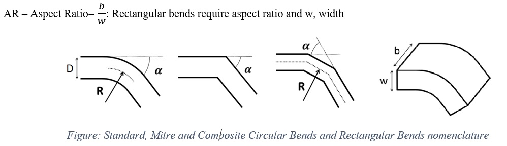
The basic bend components (geometric inputs) are shown below, where
R – Bend Radius: Radius of the bend to the centerline of the tube
D – Diameter: Tube diameter
α – Angle: Bend Angle for Standard and Mitre types of bends, and Total Swept Angle for Composite type of bends (for example; a composite Mitre bend of 3x300 means 3 individual bends of 300 bend angle. Therefore, total swept angle is 900)
Apart from these, inputs related to momentum loss are required if K-Loss options are selected (details can be found in Momentum Losses Section). Descriptions about each input is described below in “Bend Elements Inputs” section.
Bend Element Inputs
Table of the inputs specific for the Bend Elements.
| Index | UI Name (. flo label) | Description |
| 1 | SUBTYPE (SUB_TYPE) |
Subtype of the Bend Element; 1: Standard Circular 2: Circular Composite 3: Circular Mitre 4: Standard Rectangular 5: Rectangular Composite Mitre 6: Rectangular Mitre |
| 2 | Flow Equation Type (FLUID_MODE) |
User can select one of the three flow solution algorithms: 1: Compressible Gas 2: Incompressible Gas 3: Incompressible Liquid |
| 3 | Bend Angle or Total Swept Angle (BEND_ANGLE) |
Angle between the inlet tangent and exit tangent of the bend. Note 1: Total Swept Angle used for Circular Composite and Rectangular Composite Mitre types of bend elements. It is sum of the bend angles of all individual bends in that bend composition. Note 2: The maximum bend angle is 180°. |
| 4 | Bend Radius (BEND_RADIUS) |
Radius of bend along tube centerline. Used for: Standard Circular, Circular Composite, Standard Rectangular, Rectangular Composite Mitre Note 1: In Rectangular shaped bends, R/W ratio is used Note 2: Radius is the inverse of the bend’s curvature. |
| 5 | Diameter (HYD_DIAM) |
Tube diameter (or hydraulic diameter) Used for: Standard Circular, Circular Composite, Circular Mitre |
| 6 | Width (WIDTH) |
Width of Duct shaped bends Width is the distance from inside the elbow to outside the elbow Used for: Rectangular subtypes |
| 7 | Aspect Ratio (ASPECT_RATIO) |
Aspect Ratio is Where: b: Breadth (also called Height) is the distance from one end of the duct bend to the other end w: Width Used for: Rectangular subtypes Note: In order to obtain accurate results, it is emphasized that aspect ratio and loss data selection should be consistent. For example, loss data available in Fig 9.6 of (Miller, 1990) corresponds to an aspect ratio of 0.5. Therefore, the solution is accurate when the same aspect ratio is provided as an input. In fact, users are free to input any aspect ratio regardless of the selected loss data. However, it is user’s responsibility to validate such a modeling approach since there is no correction applied for aspect ratio. |
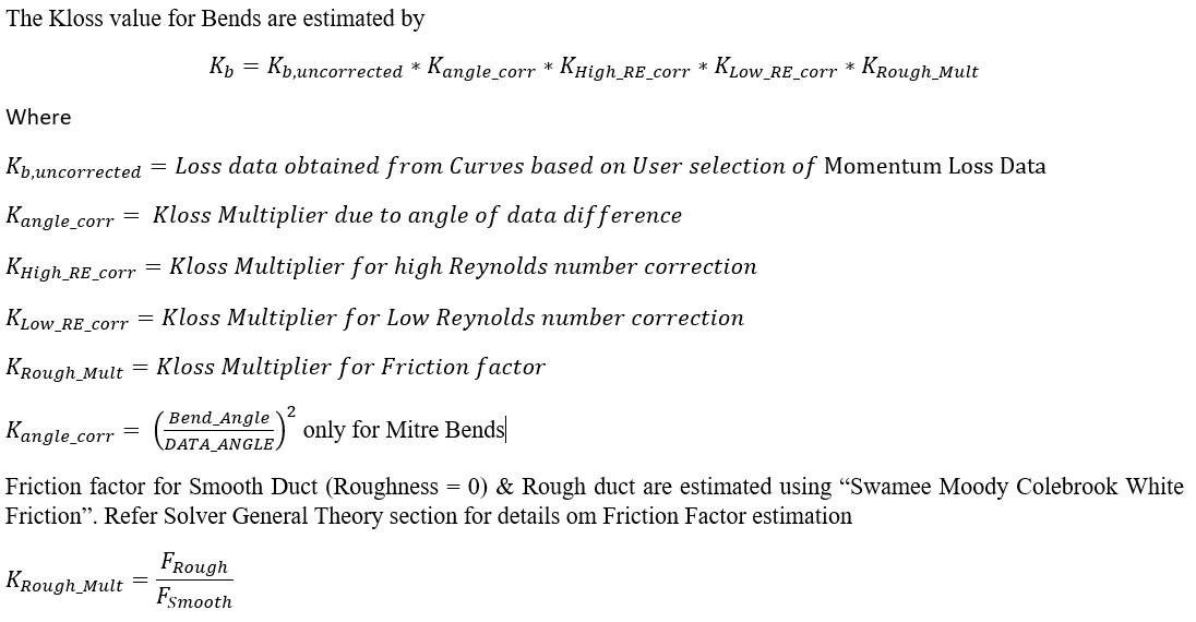
| 8 | Roughness (ROUGHNESS) | Users can either select one of the predefined roughness values (based on Cole-brook-White Roughness Values), or give a value |
| 9 | Element Inlet Orientation: Tangential Angle (THETA) |
Angle between the element centerline at the entrance of the element and the reference direction. If the element is rotating or directly connected to one or more rotating elements, the reference direction is defined as parallel to the engine centerline and the angle is the projected angle in the tangential direction. Otherwise, the reference direction is arbitrary but assumed to be the same as the reference direction for all other elements attached to the upstream chamber.
THETA for an element downstream of a plenum chamber has no impact on the solution except to set the default value of THETA_EX. (See also THETA_EX) |
| 10 | Element Inlet Orientation: Radial Angle (PHI) |
Angle between the element centerline at the entrance of the element and the THETA direction. (spherical coordinate system)
PHI for an element downstream of a plenum chamber has no impact on the solution except to set the default value of PHI_EX. (See also PHI_EX) |
| 11 | Element Exit Orientation: Tangential Angle (THETA_EX) |
Angle between the orifice exit centerline and the reference direction. THETA_EX is an optional variable to be used if the orientation of the element exit differs from that of the element inlet.
The default value (THETA_EX = -999) will result in the assumption that THETA_EX = THETA.
Other values will be interpreted in the manner presented in the description of THETA. |
| 12 | Element Exit Orientation: Radial Angle (PHI_EX) |
Angle between the orifice exit centerline and the THETA_EX direction.
PHI_EX is an optional variable to be used if the orientation of the element exit differs from that of the element inlet.
The default (PHI_EX = -999) will result in the assumption that PHI_EX = PHI.
Other values will be interpreted in the manner presented in the description of PHI. |
| 13 | Portion of Ustrm Chamb. Dyn. Head Lost (DQ_IN) | Inlet dynamic head loss. Refer General solver theory sections for more details about this input |
| 14 | Rotor Index (RPMSEL) |
Reference rotor index for user-supplied swirl. Stationary (Database Value = 0.0) Rotor 1 (Database Value = 1.0): Points to general data Shaft 1 Rotor Speed. Rotor 2 (Database Value = 2.0): Points to general data Shaft 2 Rotor Speed Rotor 3 (Database Value = 3.0): Points to general data Shaft 3 Rotor Speed |
| 15 | Data Angle (DATA_ANGLE) |
This input allows users to use specify a different (approximate) bend angle for looking up loss-coefficients. Specifying DATA_ANGLE will be helpful if the user models a 47° bend and would prefer to use the 45° K-loss curve instead of interpolating. Note: This option is valid both for Circular Composite and Rectangular Composite Mitre subtypes |
| 16 | Combination Angle Upstream (COMB_ANG_UP) |
*Not implemented Combination angle (degrees) with upstream bend if there is one |
| 17 | Combination Angle Downstream (COMB_ANG_DN) |
*Not implemented Combination angle (degrees) with downstream bend if there is one |
| 18 | Momentum Loss Data (LOSS_TYPE) |
The available K-Loss inputs are: 0: User-Specified K-Loss value
2: Blevins Data (YFT Implemented) (Blevins, 2003)
For the rest of the options, K-Loss is interpolated from K-Loss Curve Data given in the References and K-Loss Multiplier should be given by User if necessary 3: Circular Cross Section K-Loss Table [Fig. 9.6 in (Miller, 1990) 2nd Ed.] 4: Rectangular Cross-Section AR = 0.5 [Fig. 9.6 in (Miller, 1990) 2nd Ed.] 5: Rectangular Cross-Section AR = 1 [Fig. 9.7 in (Miller, 1990) 2nd Ed.] 6: Rectangular Cross-Section AR = 2 [Fig. 9.8 in (Miller, 1990) 2nd Ed.] 7: Mitre Bend [Fig. 9.9 in (Miller, 1990) 2nd Ed.] 8: Composite Mitre Bend Circular Arc [Fig. 9.10 in (Miller, 1990) 2nd Ed.] 9: Composite Mitre Bend 2x45 [Fig. 9.10 in (Miller, 1990) 2nd Ed.] 10: Composite Mitre Bend 3x30 [Fig. 9.10 in (Miller, 1990) 2nd Ed.] 11: Composite Mitre Bend 4x22.5 [Fig. 9.10 in (Miller, 1990) 2nd Ed.] Note:
|
| 19 | Low Reynolds Number K-Correction (Re<10000) (LOW_RE_CORR) |
This correction converts fully turbulent K-loss from experimental data into physical K-loss that occurs for Low Reynolds. Available options are: 0: None 2: Miller Laminar to Turbulence Loss Coefficient Ktur=0.5 [Fig. 14.32 in (Miller, 1990) 2nd Ed.] 3: Miller Laminar to Turbulence Loss Coefficient Ktur=1 [Fig. 14.32 in (Miller, 1990) 2nd Ed.] 4: Miller Laminar to Turbulence Loss Coefficient Ktur=5 [Fig. 14.32 in (Miller, 1990) 2nd Ed.] 5: Miller Laminar to Turbulence Loss Coefficient Ktur=10 [Fig. 14.32 in (Miller, 1990) 2nd Ed.] |
| 20 | High Reynolds Number K-Correction (Re>10000) (HIGH_RE_CORR) |
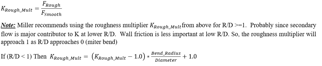
Correction that converts fully turbulent K-loss from experimental data into physical K-loss that occurs for high Reynolds numbers (and depends on Bend Radius / Pipe Diameter). 0: None 2: Bend Radius / Pipe Diameter = [Fig. 9.3 in (Miller, 1990) 2nd Ed.] 3 Bend Radius / Pipe Diameter > 2 [Fig. 9.3 in (Miller, 1990) 2nd Ed.] |
| 21 | K-Loss Multiplier (LOSS_MULT) | Loss multiplier for each bend (Default = 1.0) |
| 22 | (K_FIXED) | When Option 0 is selected for Momentum Loss Data, user should satisfy a constant K-Loss value (see Index#18) |
| 23 | Roughness Type (ROUGH_TYPE) |
This tells what type of rough the ROUGHNESS value is. 0: Sand-Grain Roughness 1: Average-Absolute Roughness 2: Root-Mean-Square Roughness 3: Peak-to-Valley Roughness |
| 24 | Laminar to Transition Reynolds Number (RE_LAM) |
Reynolds number below which flow is assumed to be laminar Note: Used only for K-correction based on wall roughness |
| 25 | Transition to Turbulent Reynolds Number (RE_TURB) |
Reynolds number above which flow is assumed to be turbulent. Flow at Reynolds numbers between RE_LAM and RE_TURB are assumed to be in the transition region. Note: Used only for K-correction based on wall roughness |

Bend Element Theory Manual
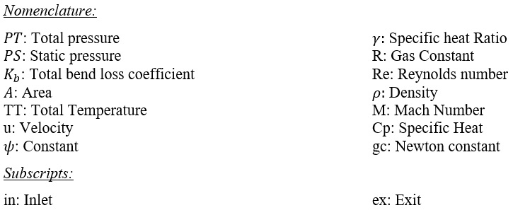
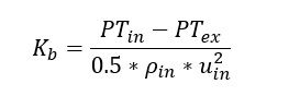
An iterative method is employed to solve conservation of mass and momentum equations for flow rate that produces required pressure loss across the bend. Here, the pressure loss is the difference between the total pressure at the inlet and static pressure at the exit of the bend and the required pressure loss means, the resultant exit pressure should match the actual static pressure at the exit. Bend element solver sends derivatives of flow rate with respect to upstream total and downstream static pressures to Flow Simulator’s main solver, after satisfying the required pressure loss.
Kloss Calculations
Flow Rate Calculations
Governing Equations for Incompressible Flow in a Bend Element
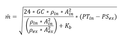
When Incompressible Gas or Incompressible Liquid is selected as Flow Type (see Index 2 in Bend Element Inputs), Bend’s loss coefficient is then defined as incompressible loss coefficient (Blevins, 2003) (Miller, 1990).
Flow Simulator uses exit static pressure instead of exiting total pressure. Applying this along with the continuity equation and after some trivial algebraic manipulations, one can obtain incompressible bend flow function as
Governing Equations for Compressible Flow in a Bend Element
For a compressible flow the continuity equation is given as follows;
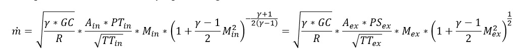
Moreover, (Miller, 1990) defines the momentum equation for compressible bends using the incompressible loss coefficient relation as shown below:
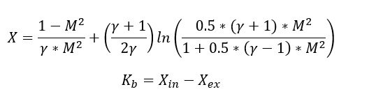
Bend element employs a Newton-Raphson method to solve coupled continuity and momentum equations to Mass Flow rate
Bend Element Outputs
Outputs in file with “res” extension. Output units controlled by user setting in “Output Control” panel.
![]()
| Name | Description | Units ENG, SI |
|---|---|---|
| BEND SOLVER STAT | ||
| BEND_NEWTON_LOOP |
Gives information about Bend element solution. A list of possible outputs is as follows:
|
(None) |
| BEND_NEWTON_ITER # | At which Newtonian iteration Bend solution has converged | (None) |
| MOMENTUM_EQN_ERROR |
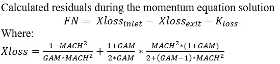 |
(None) |
| USER INPUT OPTIONS | ||
| SUBTYPE |
Subtype of Bend Element:
|
(None) |
| FLUID_MODE |
Fluid compressibility option
|
(None) |
| LOSS_DATA_REF |
Information about Momentum Loss Data.
|
(None) |
| LOW_RE_CORR |
Information about Low Reynolds Correction correlation
|
(None) |
| HIGH_RE_CORR |
Information about High Reynolds Correction correlation
|
(None) |
| INPUT_ROUGHNESS_TYPE |
Information about selected Roughness type
|
(None) |
| ELEMENT/FLOW ORIENTATION | ||
| ELEMENT_THETA_INLET, ELEMENT_PHI_INLET, REL_INLET_ANGLE | User defined inlet tangential, radial and relative angles (copy from input) | deg |
| ELEMENT_THETA_EXIT, ELEMENT_PHI_EXIT | User defined inlet tangential and radial angles (copy from input) | deg |
|
FLUID_THETA_EXIT FLUID_PHI_EXIT |
|
deg |
| ELEMENT RPM | Rotational speed of the restriction, RPM = 0 for Stationary | rev/min |
| INLET RADIUS, EXIT RADIUS | Inlet radius and exit radius of rotor | inch, m |
| INLET/EXIT LOSS FACTORS | ||
| DQ_IN | Inlet dynamic head loss (copy of input) | inch, m |
| USER_FIXED_K | K-Loss value if FIXED LOSS COEFFICIENT option selected as Momentum Loss Data (copy of input) | (unitless) |
| ROUGHNESS | Roughness value (copy of input) | inch, m |
| BEND GEOMETRY | ||
| ANGLE | Bend Angle (copy of input) | deg |
| RAD/DIA | Ratio of the Bend Radius to the Tube Diameter | (unitless) |
| HYDRAULIC_DIAM | Tube Diameter (copy of input) | inch, m |
| LOSS RESULTS | ||
| BEND_K_TOTAL | Total calculated loss coefficient | (unitless) |
| EQUIV STRAIGHT FL/D | Loss due to friction | (unitless) |
| COMPR_LOSS_COEFF |
 |
(unitless) |
| BEND_PRESSURE_DROP |
|
psia, MPa |
| LOSS_MULT | Weighting factor of K-Loss | (unitless) |
| ROUGH_MULT | K-Loss multiplier due to F_rough/F_smooth | (unitless) |
| LOW_RE_MULT | Loss coefficient multiplier for Re < 10000 (copy of input) | (unitless) |
| HIGH_RE_MULT | Loss coefficient multiplier for Re > 10000 (copy of input) | (unitless) |
| DATA_ANGLE_MULT |
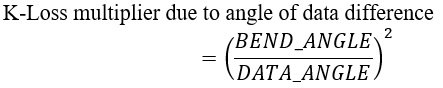 |
(unitless) |
| REYNOLDS NUMBER (Flow Type) |
Calculated Reynolds number Flow Types: Laminar Flow, Transitional Flow, Turbulent Flow Note: If user selects “Specify Transition” option, the specified values used to determine flow type. Otherwise: 0<REYNOLDS NUMBER<2000: Laminar Flow 2000<REYNOLDS NUMBER<4000: Transitional Flow 4000<REYNOLDS NUMBER: Turbulent Flow |
(None) |
| ELEMENT RESULTS | ||
| PTS | Driving pressure relative to the rotational reference frame (i.e. rotor) at the transition inlet. | psia, MPa |
| PSIN |
Static pressure relative to the rotational reference frame (i.e. rotor) at the transition inlet. Limited by critical pressure ratio for supersonic flows when inlet area is smaller than exit area. |
psia, MPa |
| PTEX | Total pressure relative to the rotational reference frame (i.e. rotor) at the transition exit including supersonic effects. | psia, MPa |
| PSEX |
Static pressure relative to the rotational reference frame (i.e. rotor) at the transition exit. Limited by critical pressure ratio for supersonic flows. |
psia, MPa |
| TTS | Total temperature of fluid relative to the rotational reference frame (i.e. rotor) at the transition inlet. | deg F, deg K |
| TSIN | Static temperature of fluid relative to the rotational reference frame (i.e. rotor) at the transition inlet. | deg F, deg K |
| TTEX | Total temperature of fluid relative to the rotational reference frame (i.e. rotor) at the transition exit. | deg F, deg K |
| TSEX | Static temperature of fluid relative to the rotational reference frame (i.e. rotor) at the transition exit. | deg F, deg K |
| VEL_IN | Velocity of fluid relative to the rotational reference frame (i.e. rotor) at the transition inlet. | ft/s, m/s |
| MACH_IN | Mach number of fluid relative to the rotational reference frame (i.e. rotor) at the transition inlet. | (unitless) |
| VEL_EX | Velocity of fluid relative to the rotational reference frame (i.e. rotor) at the transition exit. | ft/s, m/s |
| MACH_EX | Mach number of fluid relative to the rotational reference frame (i.e. rotor) at the transition exit. | (unitless) |
| K_EQV_ORIF | Incompressible Loss Coefficient K | (unitless) |
| CD_RESULT | Result calculated from actual mass flow rate divided by ideal mass flow rate. The ideal mass flow rate assumes either K=0, Cp=Cp_ideal, or Effec=1. | (unitless) |
| VOL_FLOW | Volumetric flow rate | USgpm, m3/s |
| MATERIAL PROPERTIES | ||
| RHO_IN | Density at Bend inlet conditions | Lbm/ft3, kg/m3 |
| RHO_EX | Density at Bend exit conditions | Lbm/ft3, kg/m3 |
| CP_IN | Specific Heat at constant pressure at bend inlet conditions | B/LbmDegF, J/kg/K |
| CP_EX | Specific Heat at constant pressure at bend exit conditions | B/LbmDegF, J/kg/K |
| MU_IN | Dynamic Viscosity at Bend inlet conditions | Lbm/HrFt, kg/m/s |
| MU_EX | Dynamic Viscosity at Bend exit conditions | Lbm/HrFt, kg/m/s |
| FS_IN | Steam fraction at the Bend inlet | (unitless) |
| FS_EX | Steam fraction at the Bend exit | (unitless) |
| GAM_IN | Specific Heat Ratio at Bend inlet conditions | (None) |
| GAM_EX | Specific Heat Ratio at Bend exit conditions | (None) |
| RGAS_IN | Gas constant at Bend inlet conditions | ft-lbf/lbm-R, J/kg/K |
| RGAS_EX | Gas constant at Bend exit conditions | ft-lbf/lbm-R, J/kg/K |
References
- Blevins, R. D. (2003). Applied Fluid Dynamics Handbook. Krieger Publications.
- Kreyszig, E. (1999). Advanced Engineering Mathematics, 8th Ed. John Wiley & Sons.
- Miller, D. (1990). Internal Flow Systems - Miller Innovations.