Elevation Element
Elevation Element General Description & Quick Guide
![]()
Elevation Element (gravitational orifice) is similar to Orifice element is used to calculate orifice flow including the effect of gravity and rotation. Elevation Element uses an input of Orifice mechanical Area/Diameter & Loss parameters and Gravitational effects (Inlet & Exit Heights). Loss Parameter can be Cd (Coefficient of discharge) or Incompressible Loss Coefficient (K). Elevation element can be found under both “Compressible Gas Elements” & “Incompressible Liquid Elements” section.
Elevation Element Inputs
Table of the inputs for the Elevation Element.
| Element Specific Conventional Orifice Element Input Variables | ||
| Index | UI Name (. flo label) | Description |
| 1 | Cross-Section Shape (CS_SHAPE) |
Cross-section shape allows user to specify geometry in three different ways; (-1): Area is not set (1): Arbitrary shape with Area (2): Circular with Diameter |
| 2 | Exit Area (EXIT_AREA) |
User defined exit area used to calculate exit conditions. Required if CS_SHAPE flag is 1. |
| 3 | Exit Diameter (EXIT_DIAM) |
User defined exit diameter of elevation element used to calculate exit conditions. Required if CS_SHAPE flag is 2. |
| 4 | Loss Mode (LOSS_MODE) |
Loss mode type flag: (1): Cd – Compressible Loss Coefficient (2): K – Incompressible Loss Coefficient |
| 5 |
Cd – Compressible Loss Coefficient Or K – Incompressible Loss Coefficient |
Cd or K-Loss Value. Input Limits: 0 < CD < 1 K>0 |
| 6 | Rotor Index (RPMSEL) |
Reference rotor index for user-supplied swirl. Stationary (Database Value = 0.0) Rotor 1 (Database Value = 1.0): Points to general data Shaft 1 Rotor Speed. Rotor 2 (Database Value = 2.0): Points to general data Shaft 2 Rotor Speed Rotor 3 (Database Value = 3.0): Points to general data Shaft 3 Rotor Speed Rotates with Air (database Value = -1.0): Element RPM is based on upstream fluid RPM |
| 7 | Inlet Radius (INLET_RADIUS) |
Radial distance between the orifice inlet center and the engine centerline. (Do not use zero unless the orifice is not rotating) |
| 8 | Exit Radius (EXIT_RADIUS) |
Radial distance between the orifice inlet center and the engine centerline. (Do not use zero unless the orifice is not rotating) |
| 9 | Inlet Height (INLET_HEIGHT) | Inlet elevation to be used in pressure correction calculations |
| 10 | Exit Height (EXIT_HEIGHT) | Exit elevation to be used in pressure correction calculations |
| 11 | Portion of Ustrm Chamb. Dyn. Head Lost (DQ_IN) | Inlet dynamic head loss. Refer General solver theory sections for more details about this input |
| 12 | Gravity Multiplier (GRAV_MULT) | Gravity multiplier |
| 13 | Element Inlet Orientation: Tangential Angle (THETA) |
Angle between the element centerline at the entrance of the element and the reference direction. If the element is rotating or directly connected to one or more rotating elements, the reference direction is defined as parallel to the engine centerline and the angle is the projected angle in the tangential direction. Otherwise, the reference direction is arbitrary but assumed to be the same as the reference direction for all other elements attached to the upstream chamber.
THETA for an element downstream of a plenum chamber has no impact on the solution except to set the default value of THETA_EX. (See also THETA_EX) |
| 14 | Element Inlet Orientation: Radial Angle (PHI) |
Angle between the element centerline at the entrance of the element and the THETA direction. (spherical coordinate system)
PHI for an element downstream of a plenum chamber has no impact on the solution except to set the default value of PHI_EX. (See also PHI_EX) |
| 15 |
Exit K Loss: Axial (K_EXIT_Z) Tangential (K_EXIT_U) Radial (K_EXIT_R) |
Head loss factors in the Z, U, and R directions based on the spherical coordinate system of theta and phi. (Default value provides no loss).
Refer General solver theory sections for more details about this input |
| 16 | Element Exit Orientation: Tangential Angle (THETA_EX) |
Angle between the orifice exit centerline and the reference direction. THETA_EX is an optional variable to be used if the orientation of the element exit differs from that of the element inlet.
The default value (THETA_EX = -999) will result in the assumption that THETA_EX = THETA.
Other values will be interpreted in the manner presented in the description of THETA. |
| 17 | Element Exit Orientation: Radial Angle (PHI_EX) |
Angle between the orifice exit centerline and the THETA_EX direction.
PHI_EX is an optional variable to be used if the orientation of the element exit differs from that of the element inlet.
The default (PHI_EX = -999) will result in the assumption that PHI_EX = PHI.
Other values will be interpreted in the manner presented in the description of PHI. |
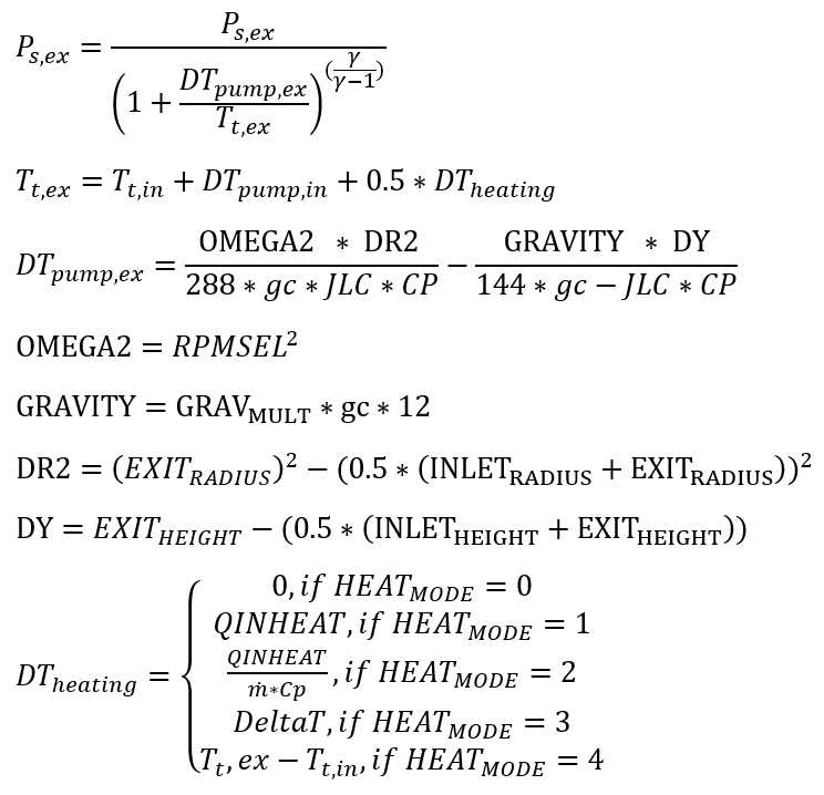
| 18 | Heat Addition Mode (HEAT_MODE) |
This tells the solver how to interpret QINHEAT. 0: Adiabatic 1: Heat addition 2: Head addition proportional to element mass flow rate 3: Delta Total temperature 4: Fixed Fluid Total temperature at exit |
| 19 | Heat Added (QINHEAT) |
Heat Added – if Heat Mode =1 or 2 Delta.T – if Heat Mode =3 Fixed total temperature at exit = 4 |
| 20 | Fluid Compressibility Mode (FLUID_MODE) |
The user can choose which solution algorithm to use. 1: Compressible Gas 2: Incompressible Gas 3: Incompressible liquid |
Elevation Element Theory Manual
The flow function written to define the flow through an elevation element in terms of upstream total pressure, upstream total temperature, downstream static pressure and cross-sectional flow area. Since the flow function is derived with the assumption of isentropic flow, some sort of empirical correction is required to account for the irreversible losses encountered in the Orifices. This is usually contained in form of a discharge coefficient or Loss coefficient, included in the working definition of flow function and represents the ratio of actual (empirical) to ideal (isentropic) flow rates.
| Nomenclature: | |
| W: Mass flow rate | |
| A: Orifice mechanical area | R: Gas Constant |
| CD: Coefficient of Discharge | Ts: Static Temperature |
| K: Incompressible Loss Coefficient | |
| Tt: Total Temperature | MN: Vena Contracta Mach Number |
| Pt: Total pressure | Cp: Specific Heat |
| Ps: Static pressure |
gc: Gravitational Constant JLC = 778.169 |
Discharge Loss Coefficient Calculations
Loss Mode: Cd – Compressible Loss Coefficient
![]()
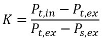
Loss Mode: K – Incompressible Loss Coefficient
![]()
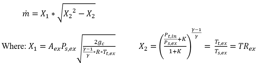
Flow Rate Calculations
These equations can be used to derive an expression for mass flow rate, .
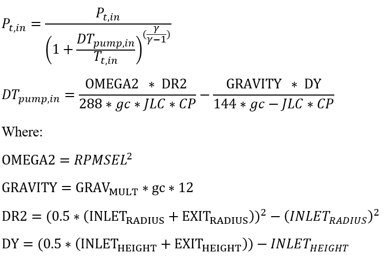
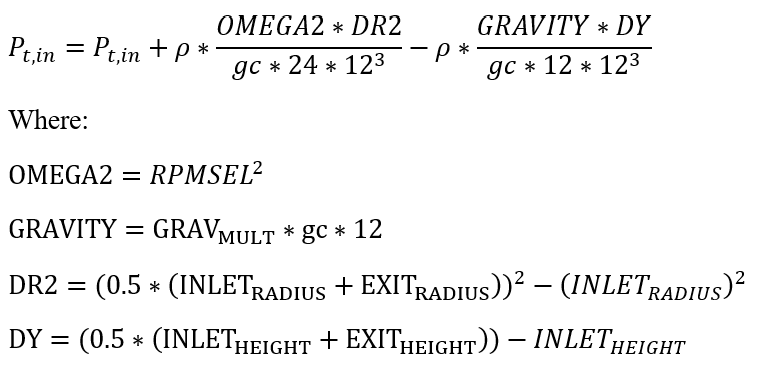
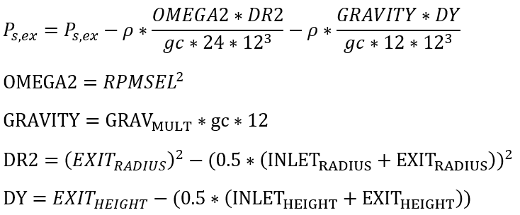
In the above equations, the corrected pressures (for the effects of Gravity & Pumping) will be used, which are defined below
Compressible and Incompressible Gas Conditions:
Inlet Conditions:
Exit Conditions:
Incompressible Liquid Conditions:
Inlet Conditions:
Exit Conditions:
Elevation Element Outputs
The following listing provides details about conventional orifice output variables.
| Name | Description | Units |
|---|---|---|
|
FLOWS: FLOW: %WREF & MASSFLOWRATE |
Flow rates in %WREF and [PPS]or [kg/s] | (None) & (PPS or kg/s) |
| SOLVER_STAT | Information on status of the elevation element solution | Flag |
| FLUID: | Fluid equation type information | Flag |
| CHOKED_FLOW_SOLVER_STAT | Convergency information | Flag |
| NEWTON_ITERS: | How many iterations before non-convergence | Flag |
| ERROR: | Error value if the solver does not converge to solve elevation element | Unitless |
| DQ_IN |
Portion of Ustrm Chamb. Dyn. Head Lost (Usually an echo of the user input unless modified inside Flow Simulator.) |
Flag |
|
Axial (K_EXIT_Z) Tangential (K_EXIT_U) Radial (K_EXIT_R) |
Exit K Loss (Usually an echo of the user input unless modified inside Flow Simulator.)
|
Unitless |
| ELEMENT_THETA |
Tangential Angle (Usually an echo of the user input but converted to radians.) |
radians |
| ELEMENT_PHI |
Radial Angle (Usually an echo of the user input but converted to radians.) |
radians |
| REL_INLET_ANGLE | It is a relative inlet angle calculated based on upstream chamber velocity | Deg |
| ELEMENT_RPM |
RPM (Rotor index) (Usually an echo of the user input unless modified inside Flow Simulator.) |
rad/min |
| RIN |
Radius (Usually an echo of the user input unless modified inside Flow Simulator.) |
in, m |
| REX |
Radius (Usually an echo of the user input unless modified inside Flow Simulator.) |
in, m |
| GRAV_MULT | Gravity Multiplier | |
| INLET_HEIGHT |
Inlet Height (Usually an echo of the user input unless modified inside Flow Simulator.) |
in,m |
| EXIT_HEIGHT |
Exit Height (Usually an echo of the user input unless modified inside Flow Simulator.) |
in,m |
| ELEMENT_AREA |
Cross-sectional area. (Usually an echo of the user input unless modified inside Flow Simulator.) |
inch2, m2 |
| CD |
Discharge coefficient. (Usually an echo of the user input unless modified inside Flow Simulator.) |
(fraction) |
| K |
Head loss coefficient. Calculated from the discharge coefficient using equation |
(unitless) |
| EXIT_AREA |
Exit area used for calculating exit conditions of the orifice element. This output is only printed when an exit area is used (EXIT_AREA>0). A default value of 0 has no effect on exit conditions. (Output is an echo of the user input.) |
inch2, m2 |
| PTS | Driving pressure relative to the rotational reference frame (i.e. rotor) at the restriction inlet. | psi, mPa |
| PTEX | Total pressure relative to the rotational reference frame (i.e. rotor) at the restriction exit including supersonic effects. | psi, mPa |
| PSEX |
Static pressure relative to the rotational reference frame (i.e. rotor) at the restriction exit. Limited by critical pressure ratio for supersonic flows. |
psi, mPa |
| PSEB | Effective sink (static) pressure downstream of the restriction. | psi, mPa |
| TTS | Total temperature of fluid relative to the rotational reference frame (i.e. rotor) at the restriction inlet. | deg F, K |
| VCMN | Fluid Mach number relative to the rotational reference frame (i.e. rotor) at the vena contracta. | (unitless) |
| VXA | Fluid velocity relative to the rotational reference frame (i.e. rotor) at the restriction exit before heat input (QIN) effects. | ft/s, m/s |
| EXMN | Fluid Mach number relative to the rotational reference frame (i.e. rotor) at the restriction exit before heat input (QIN) effects. | (unitless) |
| QIN |
Heat input. Positive values indicate heat added to the fluid; negative values indicate heat removed. |
BTU/s, W |
| DT | Change in total temperature relative to the rotational reference frame (i.e. rotor) due to heat input (QIN). | deg F, K |
| TEX | Total temperature relative to the rotational reference frame (i.e. rotor) at the restriction exit. | deg F, K |
| VEX | Fluid velocity relative to the rotational reference frame (i.e. rotor) at the restriction exit including heat input (QIN) effects. | ft/s, m/s |
| VABS | Magnitude of the fluid total absolute velocity | ft/s, m/s |
| VTAN_ABS | Magnitude of the fluid absolute tangential velocity | ft/s, m/s |
| VAXIAL | Magnitude of the fluid axial velocity | ft/s, m/s |
| VRAD | Magnitude of the fluid radial velocity | ft/s, m/s |
| THTA_ABS | Fluid absolute tangential flow angle | rad |
| VREL | Magnitude of the fluid total velocity relative to the element | ft/s, m/s |
| VTAN_REF | Reference frame tangential velocity | ft/s, m/s |
| VTAN_REL | Magnitude of the fluid tangential velocity relative to the element | ft/s, m/s |
| VNORM | Magnitude of the fluid total velocity relative to the element | ft/s, m/s |
| THTA_REL | Fluid relative tangential flow angle | rad |
| TTABS | Absolute total temperature | deg F, K |
| TTREL | Relative total temperature | deg F, K |