Orifice Element
Orifice General Description
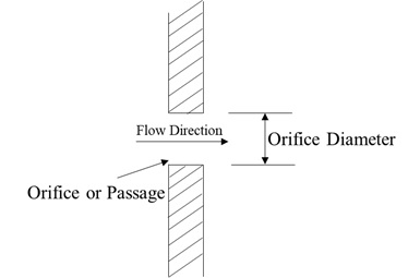
Orifice element provides a way of modelling a pressure loss between two chambers within a system, where the only purpose of the element is to model a flow restriction with losses within the system (for example a simple aperture, coolers, strainers, fittings, leakages or sudden changes in cross-section). The orifice may be fixed in space or rotating about the engine centerline and each may be positioned at any angle relative to the coordinate system. Orifice elements uses an input of Orifice mechanical Area/Diameter & Loss parameters with a standard isentropic flow relationship to calculate the element flow rates. Loss Parameter can be Cd (Coefficient of discharge) or Incompressible Loss Coefficient (K). This element does not model any fluid inertia.
Quick Guide for Orifice Element Creation in the GUI
There are different subtypes of Orifices elements available in FlowSimulator. All the orifice elements can be used in Compressible (e.g. gas systems) and Incompressible (e.g. hydraulic and non-hydraulic systems) analysis. The various subtypes are
Conventional Orifice

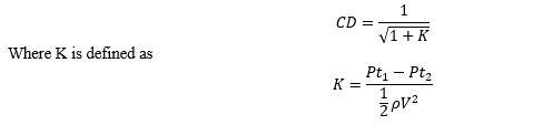
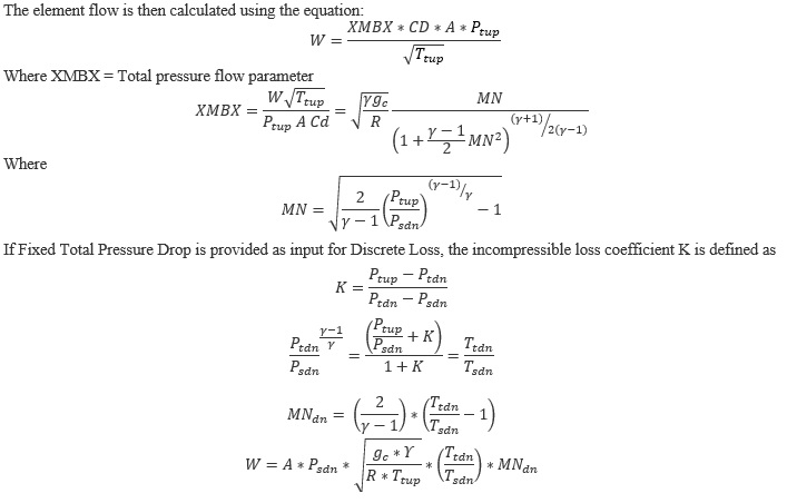
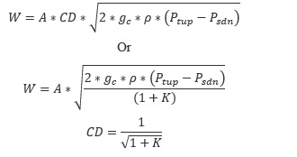
Conventional orifice is a standard orifice element where you need to provide mandatory inputs Cross sectional Area or Diameter and CD or K value. User can convert the conventional orifice to Nozzle by providing the Nozzle efficiency. Cd (discharge coefficient) for an Orifice element can be between any value between 0+ and 1.0 as input. The Users can also provide Incompressible Loss coefficient (K) as input. Allowable Kloss Values are from 0 to 10. The discharge coefficient is calculated by the incompressible relationship,
Heater Cooler

Heater Cooler is same as Conventional Orifice, but a specific subtype is created for the ease of distinction if the users need to model Flow Restrictions with Heat Addition/Removal across the restriction. All the mandate inputs remain same as like Convention orifice (Area, Loss Coefficient) along with Heat Addition mode & its required inputs. There are 4 different heat mode users can apply, they are
- Heat Addition: Specify Heat Input, (+) Input models Heat Addition & (-) Input model Heat Removal
- Heat Addition per Mass Flow: Specify Heat Input per Mass Flow.
- Fluid Delta Tt: Specify Delta Total temperature rise across orifice. (+) Input models Heat Addition & (-) Input model Heat Removal
- Fixed Fluid Tt Exit: Specify Exit Temperature of the orifice
Discrete Loss
Discreet Loss is another subtype of Conventional orifice & users will have an additional option to specify Delta Total pressure loss (Pt1-Pt2) across the restrictions directly to model restriction losses in addition to Loss Parameters option (Cd or K). Mandatory inputs Cross sectional Area or Diameter and CD or K or Delta.P (Pt1-Pt2) value. Cd (discharge coefficient) for a Discrete loss element can be between any value between 0+ and 1.0 as input. There is no input restriction on upper limit of Kloss Values for discrete loss element.
Swirl Carryover Orifice
The tangential velocity calculation for the swirl carryover orifice element is the only difference from the conventional orifice. The swirl carryover is a fraction of upstream tangential velocity that is carried over to the downstream.
Orifice Element Inputs
Table of the inputs for the Orifice Element.
| Element Specific Conventional Orifice Element Input Variables | ||
| Index | UI Name (. flo label) | Description |
| 1 |
Area (AREA) Diameter (DIA) |
Orifice mechanical area Orifice Diameter |
| 2 |
Cd – Compressible Loss Coefficient Or K – Incompressible Loss Coefficient [Head Loss] |
Cd or K Value. For All Subtypes 0 < CD < 1 For Conventional orifice, 0<K<10 & for Discrete Loss K>0 |
| 3 | Exit Area (EXIT_AREA) |
Orifice exit area is used to calculate exit conditions (To account for Additional pressure Loss due to Sudden Change in Area) If the value is 0.0, exit conditions are only based on the orifice mechanical area and losses associated with the orifice. |
| 4 | Efficiency (EFFIC) |
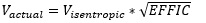
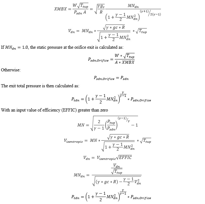
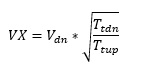
Nozzle efficiency. Entry of a number between 0.0 and 1.0 causes Flow Simulator to treat this orifice as a convergent-divergent nozzle with a nozzle efficiency of EFFIC. The flow calculation is identical to the standard orifice, but the exit velocity is calculated using the equation:
where Visentropic depends on the driving pressure ratio across the orifice. |
| 5 | Element Multiplicity factor |
A single orifice element can have multiple streams within. Number of Streams Entering: Also referred as NLU Number of Streams Leaving: Also referred as NED |
| 6 | Element Inlet Orientation: Tangential Angle (THETA) |
Angle between the element centerline at the entrance of the element and the reference direction. If the element is rotating or directly connected to one or more rotating elements, the reference direction is defined as parallel to the engine centerline and the angle is the projected angle in the tangential direction. Otherwise, the reference direction is arbitrary but assumed to be the same as the reference direction for all other elements attached to the upstream chamber.
THETA for an element downstream of a plenum chamber has no impact on the solution except to set the default value of THETA_EX. (See also THETA_EX) |
| 7 | Element Inlet Orientation: Radial Angle (PHI) |
Angle between the element centerline at the entrance of the element and the THETA direction. (spherical coordinate system)
PHI for an element downstream of a plenum chamber has no impact on the solution except to set the default value of PHI_EX. (See also PHI_EX) |
| 8 | Element Exit Orientation: Tangential Angle (THETA_EX) |
Angle between the orifice exit centerline and the reference direction. THETA_EX is an optional variable to be used if the orientation of the element exit differs from that of the element inlet.
The default value (THETA_EX = -999) will result in the assumption that THETA_EX = THETA.
Other values will be interpreted in the manner presented in the description of THETA. |
| 9 | Element Exit Orientation: Radial Angle (PHI_EX) |
Angle between the orifice exit centerline and the THETA_EX direction.
PHI_EX is an optional variable to be used if the orientation of the element exit differs from that of the element inlet.
The default (PHI_EX = -999) will result in the assumption that PHI_EX = PHI.
Other values will be interpreted in the manner presented in the description of PHI. |
| 10 | Heat Input (QIN) |
Heat input. QIN is heat added to (positive values) or removed from (negative) the fluid flowing through the orifice.
In cases where multiple flow streams are modelled by a single element (i.e. NED and NLU not equal to 1), the value of QIN should be set to model the heat flow from only one of the restrictions. |
| 11 | Portion of Ustrm Chamb. Dyn. Head Lost (DQ_IN) | Inlet dynamic head loss. Refer General solver theory sections for more details about this input |
|
12 13 14 |
Exit K Loss: Axial (K_EXIT_Z) Tangential (K_EXIT_U) Radial (K_EXIT_R) |
Head loss factors in the Z, U, and R directions based on the spherical coordinate system of theta and phi. (Default value provides no loss).
Refer General solver theory sections for more details about this input |
| 15 | Reverse Loss Coefficient (CD_REV) |
Flag for calculating the discharge coefficient, Cd, or the loss coefficient, K when the orifice flow direction is reversed. CD_REV=0, CD_REV is the same as CD (forward). |
| 17 | Rotor Index (RPMSEL) |
Reference rotor index for user-supplied swirl. Stationary (Database Value = 0.0) Rotor 1 (Database Value = 1.0): Points to general data Shaft 1 Rotor Speed. Rotor 2 (Database Value = 2.0): Points to general data Shaft 2 Rotor Speed Rotor 3 (Database Value = 3.0): Points to general data Shaft 3 Rotor Speed Rotates with Air (database Value = -1.0): Element RPM is based on upstream fluid RPM |
| 18 | Radius (RAD) |
Radius. Radial distance between the orifice inlet center and the engine centerline. (Do not use zero unless the orifice is not rotating) |
| 19 | Flow Equation Type (INCOMPR_FLG) |
Flag to specify flow compressibility for element calculations (Compressible vs. Incompressible). For incompressible flow options (1 or 2), fluid density can be calculated using either upstream or downstream static pressure. For combustor models, option 1 is usually used to model Swirler Cups, while option 2 is used to model cooling and dilution holes. 0.0: Standard Compressible Flow 3.0: Incompressible Liquid |
| 20 | Swirl CarryOver | Can be None, Fixed Swirl CarryOver . For fixed Swirl CarryOver, User need to input the value. |
Orifice Theory Manual
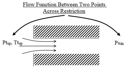
The isentropic flow function written to define the flow through an orifice restriction in terms of upstream total pressure, upstream total temperature, downstream static pressure and cross-sectional flow area. Since the flow function is derived with the assumption of isentropic flow, some sort of empirical correction is required to account for the irreversible losses encountered in the Orifices. This is usually contained in form of a discharge coefficient or Loss coefficient, included in the working definition of flow function and represents the ratio of actual (empirical) to ideal (isentropic) flow rates.
| Nomenclature: | |
| W: Mass flow rate | Specific heat Ratio |
| A: Orifice mechanical area | R: Gas Constant |
| CD: Coefficient of Discharge | Ts: Static Temperature |
| K: Incompressible Loss Coefficient | Density |
| Tt: Total Temperature | MN: Vena Contracta Mach Number |
| Pt: Total pressure | Cp: Specific Heat |
| Ps: Static pressure | gc: Gravitational Constant |
| Subscripts: | |
| up: Upstream station | b: Back |
| dn: Downstream station |
Calculation of Flow Rate and Vena Contracta Mach Number
Conventional Orifice, Heater Cooler & Discrete Loss:
For Compressible Flow Equation:
The element flow is then calculated using theequation:
For Incompressible Flow Equation:
Calculation of Orifice Exit Conditions
The flow is first expanded from the vena contracta throat to the exit conditions before any effect of heat addition, QIN, is considered. it is assumed that the flow is expanded adiabatically (limited to Mach number = 1.0) to the mechanical area of the orifice at the exit static pressure, . The static pressure exit flow parameter, exit Mach number and adiabatic exit velocity is calculated as:
The effect of heat addition specified as QIN is added next, assuming that only the exit temperature and velocity, and not the exit Mach number, are affected. The temperature rise (or drop if QIN is negative) is calculated using an average value of specific heat (Cp)
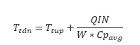
Cpavg: Specific heat at the average of TTS and TEX, pressure PSEX, and secondary fluid mass fraction FS(IC)
A new exit velocity is next calculated as:
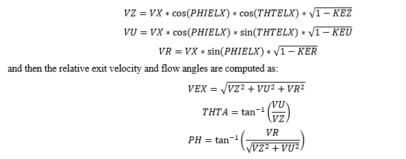
If 0 values are input for each of the exit head loss variables (KEZ, KEU and KER), the element exit velocity, VEX, is set to VX, and the relative radial and tangential flow angles at the exit plane (THTA and PH) are taken to be the values specified for the input variables THTELX and PHIELX respectively. If any of these exit head loss variables are input as non-zero values, the exit velocity components are recomputed as:
Swirl Carryover Orifice Element Tangential Velocity
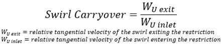
For long holes (L/D > 1) the swirl carryover is low (often near 0). This means the swirl from upstream of the restriction does not affect the swirl exiting the restriction (the rotation of the hole itself is what determines the swirl exiting the restriction).
Additional Momentum Loss
For Additional Momentum loss, Portion of Upstream Dynamic Head loss, Exit K Loss refer Solver General theory section.
Orifice Element Outputs
The following listing provides details about conventional orifice output variables.
| Name | Description | Units |
|---|---|---|
| DQ_IN |
Portion of Ustrm Chamb. Dyn. Head Lost (Usually an echo of the user input unless modified inside Flow Simulator.) |
Flag |
|
Axial (K_EXIT_Z) Tangential (K_EXIT_U) Radial (K_EXIT_R) |
Exit K Loss (Usually an echo of the user input unless modified inside Flow Simulator.)
|
Unitless |
| ELEMENT_THETA |
Tangential Angle (Usually an echo of the user input but converted to radians.) |
radians |
| ELEMENT_PHI |
Radial Angle (Usually an echo of the user input but converted to radians.) |
radians |
| REL_INLET_ANGLE | It is a relative inlet angle calculated based on upstream chamber velocity | Deg |
| ELEMENT_RPM |
RPM (Rotor index) (Usually an echo of the user input unless modified inside Flow Simulator.) |
rad/min |
| RAD |
Radius (Usually an echo of the user input unless modified inside Flow Simulator.) |
in, m |
| ELEMENT_AREA |
Cross-sectional area. (Usually an echo of the user input unless modified inside Flow Simulator.) |
inch2, m2 |
| CD |
Discharge coefficient. (Usually an echo of the user input unless modified inside Flow Simulator.) |
(fraction) |
| K |
Head loss coefficient. Calculated from the discharge coefficient using equation |
(unitless) |
| EXIT_AREA |
Exit area used for calculating exit conditions of the orifice element. This output is only printed when an exit area is used (EXIT_AREA>0). A default value of 0 has no effect on exit conditions. (Output is an echo of the user input.) |
inch2, m2 |
| PTS | Driving pressure relative to the rotational reference frame (i.e. rotor) at the restriction inlet. | psi, mPa |
| PTEX | Total pressure relative to the rotational reference frame (i.e. rotor) at the restriction exit including supersonic effects. | psi, mPa |
| PSEX |
Static pressure relative to the rotational reference frame (i.e. rotor) at the restriction exit. Limited by critical pressure ratio for supersonic flows. |
psi, mPa |
| PSEB | Effective sink (static) pressure downstream of the restriction. | psi, mPa |
| TTS | Total temperature of fluid relative to the rotational reference frame (i.e. rotor) at the restriction inlet. | deg F, K |
| VCMN | Fluid Mach number relative to the rotational reference frame (i.e. rotor) at the vena contracta. | (unitless) |
| VXA | Fluid velocity relative to the rotational reference frame (i.e. rotor) at the restriction exit before heat input (QIN) effects. | ft/s, m/s |
| EXMN | Fluid Mach number relative to the rotational reference frame (i.e. rotor) at the restriction exit before heat input (QIN) effects. | (unitless) |
| QIN |
Heat input. Positive values indicate heat added to the fluid; negative values indicate heat removed. |
BTU/s, W |
| DT | Change in total temperature relative to the rotational reference frame (i.e. rotor) due to heat input (QIN). | deg F, K |
| TEX | Total temperature relative to the rotational reference frame (i.e. rotor) at the restriction exit. | deg F, K |
| VEX | Fluid velocity relative to the rotational reference frame (i.e. rotor) at the restriction exit including heat input (QIN) effects. | ft/s, m/s |
| VABS | Magnitude of the fluid total absolute velocity | ft/s, m/s |
| VTAN_ABS | Magnitude of the fluid absolute tangential velocity | ft/s, m/s |
| VAXIAL | Magnitude of the fluid axial velocity | ft/s, m/s |
| VRAD | Magnitude of the fluid radial velocity | ft/s, m/s |
| THTA_ABS | Fluid absolute tangential flow angle | rad |
| VREL | Magnitude of the fluid total velocity relative to the element | ft/s, m/s |
| VTAN_REF | Reference frame tangential velocity | ft/s, m/s |
| VTAN_REL | Magnitude of the fluid tangential velocity relative to the element | ft/s, m/s |
| VNORM | Magnitude of the fluid total velocity relative to the element | ft/s, m/s |
| THTA_REL | Fluid relative tangential flow angle | rad |
| TTABS | Absolute total temperature | deg F, K |
| TTREL | Relative total temperature | deg F, K |