Brush Seal Element
Brush Element General Description & Quick Guide

FlowSimulator Brush Seal element models the leakage flow across the W-Seal. This can be used only in Compressible (e.g. gas systems) analysis.
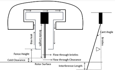
Figure: Brush Seal Inputs
Brush Seal Element Inputs
Table of the inputs for the Brush Seal Element.
| Element Specific Brush Seal Input Variables | ||
|---|---|---|
| Index | Field | Description |
| 1 | Bristle Length | Length of Bristle |
| 2 | Interference Length | Interference Length if the bristle type is Interference |
| 3 | Cold Clearance | Cold Clearance (=0 for Interference type Bristle) |
| 4 | Bristle Diameter | Diameter of the Bristle |
| 5 | Cant Angle | Angle of Bristles |
| 6 | No.of. Bristles | Number of Bristles per Circumferential length |
| 7 | Fence Height | Fence Height of the Brush Seal |
| 8 | Bristle Inner Dia | Inner Diameter of Bristle from Engine centerline |
| 9 | Bristle Outer Dia | Outer Diameter of Bristle from Engine centerline |
| 10 | Rotor Index (RPMSEL) |
Reference rotor index for user-supplied swirl. Stationary (Database Value = 0.0) Rotor 1 (Database Value = 1.0): Points to general data Shaft 1 Rotor Speed. Rotor 2 (Database Value = 2.0): Points to general data Shaft 2 Rotor Speed Rotor 3 (Database Value = 3.0): Points to general data Shaft 3 Rotor Speed Rotates with Air (database Value = -1.0): Element RPM is based on upstream fluid RPM |
| 11 | Youngs Modulus | Young Modulus |
| 12 | Swirl | Swirl Value for Swirl Carryover |
| 13 | Tip Flow equation |
Flow equation
|
| 14 | Solving methodology |
Solving methodology
|
| 15 | Element Inlet Orientation: Tangential Angle (THETA) |
Angle between the element centerline at the entrance of the element and the reference direction. If the element is rotating or directly connected to one or more rotating elements, the reference direction is defined as parallel to the engine centerline and the angle is the projected angle in the tangential direction. Otherwise, the reference direction is arbitrary but assumed to be the same as the reference direction for all other elements attached to the upstream chamber.
THETA for an element downstream of a plenum chamber has no impact on the solution except to set the default value of THETA_EX. (See also THETA_EX) |
| 16 | Element Inlet Orientation: Radial Angle (PHI) |
Angle between the element centerline at the entrance of the element and the THETA direction. (spherical coordinate system)
PHI for an element downstream of a plenum chamber has no impact on the solution except to set the default value of PHI_EX. (See also PHI_EX) |
| 17 | Element Exit Orientation: Tangential Angle (THETA_EX) |
Angle between the orifice exit centerline and the reference direction. THETA_EX is an optional variable to be used if the orientation of the element exit differs from that of the element inlet.
The default value (THETA_EX = -999) will result in the assumption that THETA_EX = THETA.
Other values will be interpreted in the manner presented in the description of THETA. |
| 18 | Element Exit Orientation: Radial Angle (PHI_EX) |
Angle between the orifice exit centerline and the THETA_EX direction.
PHI_EX is an optional variable to be used if the orientation of the element exit differs from that of the element inlet.
The default (PHI_EX = -999) will result in the assumption that PHI_EX = PHI.
Other values will be interpreted in the manner presented in the description of PHI. |
| 19 | Portion of Ustrm Chamb. Dyn. Head Lost (DQ_IN) | Inlet dynamic head loss. Refer General solver theory sections for more details about this input |
Brush Seal Element Theory Manual
Assumptions
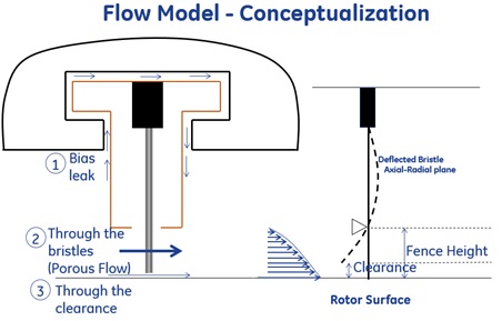
Porous Flow Model
- Flow is isothermal
- Losses due to radial flow across the bristles are not accounted
- Flow area is equal to back plate area exposed to the downstream only
- Bristle lift-off is modeled with coupling with the simplified one-dimensional deflection model
Tip clearance leak flow model
- Flow is incompressible through the clearance
- Bristles are treated to be equivalent of one tooth of lab-seal
- A constant CD = 0.6 is assumed by treated the gap as a sharp-edged orifice
Brush seal Flow calculations
| Nomenclature: | |
| : Mass flow rate | Specific heat Ratio |
| Tt: Total Temperature | R: Gas Constant |
| Pt: Total pressure | Ts: Static Temperature |
| Ps: Static pressure | ρ: Density |
| gc: Gravitational Constant | G: Mass Flux |
| D:Diamter | N: Total Number of Bristles |
| f:Friction Factor | hf:Axial Clearane |
| N_RE:Reynolds Number | θ:Cant Angle |
| Δp:Pressure Difference | Bρ:Bristle Density |
| j: Number rows in the azimuthal direction | i: Number rows in the axial direction |
| l:Length | y:Max Axial Deflection |
| Fh:Fence Height | Cc:Cold Clearance |
| BLDN:Blowdown | |
| Subscripts: | |
| in: Upstream station | ex: Downstream station |
| b:Bristle | Inter: Interference |
| b,o:Bristle Outer | b,i:Bristle Inner |
If (Cc=0) & (linter=0)→No Blow Down
If (Cc>0) & (linter=0)→Blow Down exixts
If (Cc=0) & (linter>0)→No Blow Down
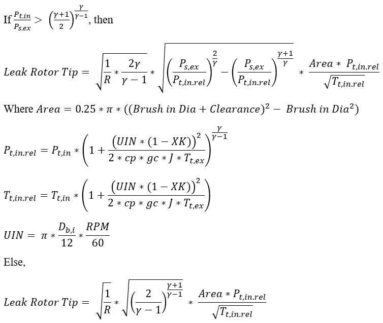
If Blow Down exists, then
Calculate “Bristle Leak” through modified Chupp method with hf=0
Calculate “Leak rotor Tip” through Alexiou /Yan/Orifice Formulation.
Calculate “Effective Thickness without Blowdown” for “Brush Leak = Bristle Leak + Leak rotor Tip” with hf=0
Calculate “Effective Thickness inline” for “Bristle Leak” with hf=0
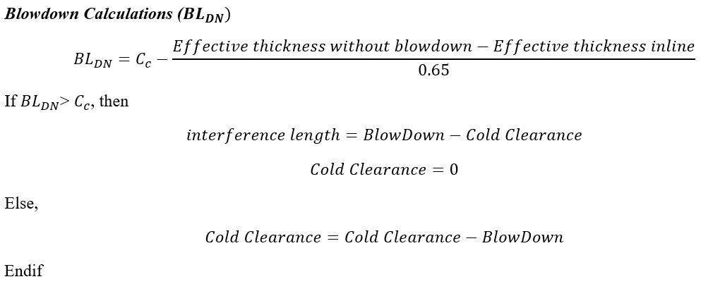
Total Mass flow rate is W=Bristle Leak+Leak Rotor Tip
-
Calculate “Bristle Leak” through modified Chupp method
-
Calculate “Leak rotor Tip” through Alexiou /Yan/Orifice Formulation.
Flow through the Bristles (Porous Flow) Modified Chupp method
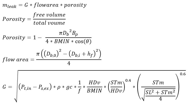
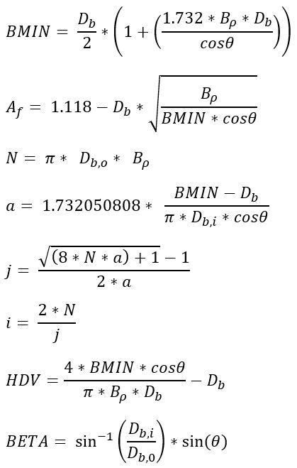
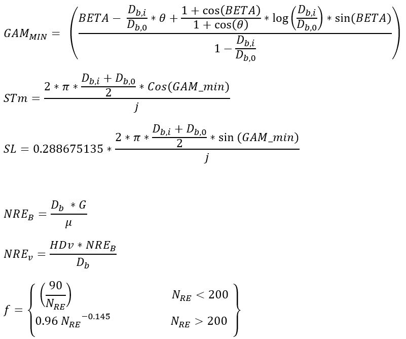
Clearance calculations – Axial (hf)
![]()
If (Clearance >=Fh), Clearance = Fh
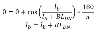
Max Axial Deflection(y)Calculation
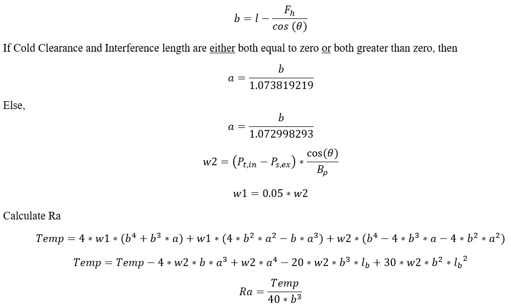
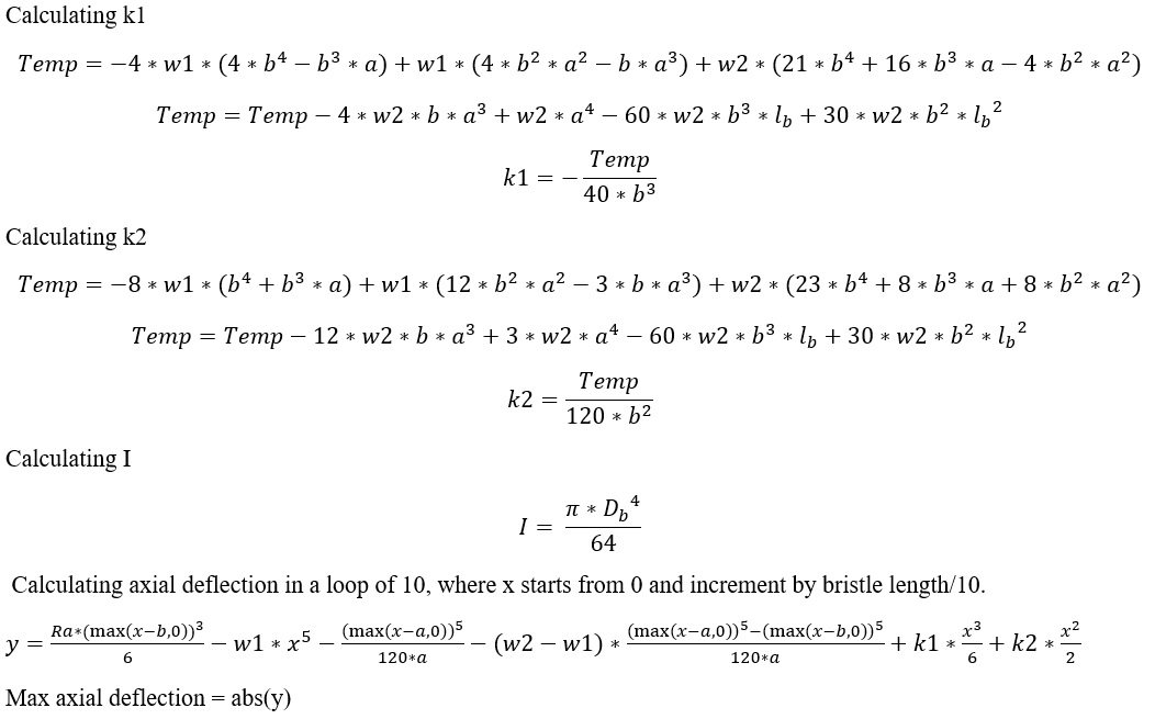
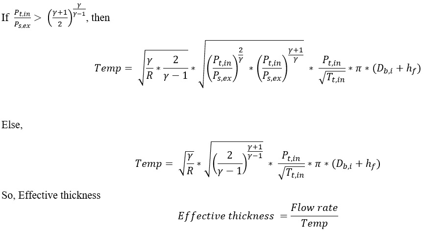
Effective Thickness Calculation
Flow Through the Rotor Tip Clearance Alexiou Model
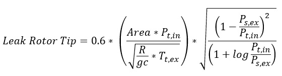
Flow Through the Rotor Tip Clearance Orifice Equation
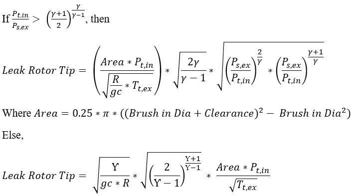
Flow Through the Rotor Tip Clearance Yans Formulation
Brush Seal Element Outputs
The following listing provides details about Brush Seal Element output variables.
| Element Specific Brush Seal Input Variables | |||
|---|---|---|---|
| Index | Field | Description | Units |
| 1 | Bristle Length | Length of Bristle (User Input) | in, m |
| 2 | Interference Length | Interference Length if the bristle type is Interference (User Input) | in, m |
| 3 | Cold Clearance | Cold Clearance (=0 for Interference type Bristle) (User Input) | in, m |
| 4 | Cant Angle | Angle of Bristles (User Input) | deg |
| 5 | Bristle Diameter | Diameter of the Bristle (User Input) | in, m |
| 6 | No.of. Bristles (Bristle Density) | Number of Bristles per Circumferential length (User Input) | 1/in, 1/m |
| 7 | Fence Height | Fence Height of the Brush Seal (User Input) | in, m |
| 8 | Youngs Modulus | Young Modulus (User Input) | psi, mPa |
| 8 | Bristle Inner Dia | Inner Diameter of Bristle from Engine centerline (User Input) | in, m |
| 9 | Bristle Outer Dia | Outer Diameter of Bristle from Engine centerline (User Input) | in, m |
| 10 | XK | Swirl (User Input) | unitless |
| 11 | RPM | Element RPM is based on upstream fluid RPM. (User Input) | Rad/min |
| 12 | Solving methodology |
Solving methodology 1.Modified Chupp |
(None) |
| 13 | Tip Flow equation |
Flow equation
|
(None) |
| 14 | BlowDown_New | BlowDown | in, m |
| 15 | Cold Clearance Calculated | Cold Clearance calculated | in, m |
| 16 | Bristle Leak | Bristle leak | Lbm/s, kg/s |
| 17 | Leak Rotor Tip | Leak Rotor tip | Lbm/s, kg/s |
| 18 | Bristle Leak with BlowDown | Bristle Leak with BlowDown | Lbm/s, kg/s |
| 19 | Leak Rotor Tip with BlowDown | Leak Rotor Tip with BlowDown | Lbm/s, kg/s |
| 20 | Brush Leak | Brush Leak | Lbm/s, kg/s |
| 21 | Effective Thickness without Blowdown | Effective Thickness without Blowdown | in, m |
| 22 | Effective thickness inline | Effective thickness inline | in, m |
| 23 | Effective thickness with Blowdown | Effective thickness with Blowdown | in, m |
| 24 | Max_Axial_Def | Max_Axial_Def | in, m |
| 25 | CLR_Axial_Def | CLR_Axial_Def | in, m |
| 26 | Clearance | Clearance | in, m |
| 27 | MDOT | Mass flow rate | Lbm/s, kg/s |
| 28 | EXMN | Exit Mach number | (None) |
| 29 | EXVEL | Exit velocity | ft/s, m/s |
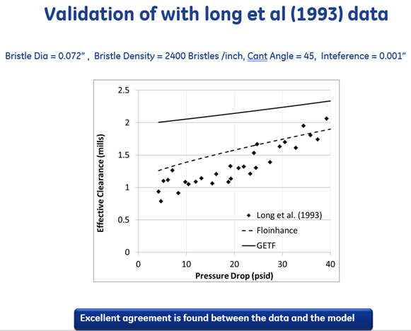
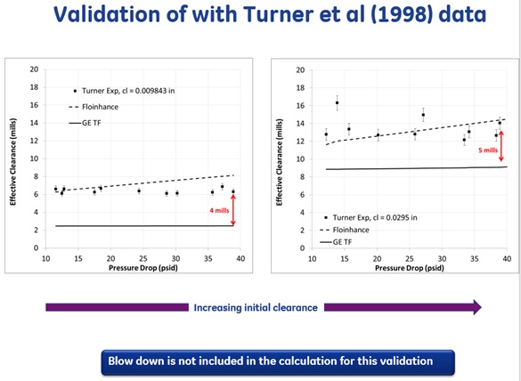
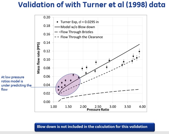
Validation
References
- Dogu, Y, Aksit, M, E., Demiroglu, M., Dinc, S, O., “Evaluation of flow behavior for clearance brush selas”, J. Engg Gas Turbines and Power, 130, 2008.
- Andres, L, S., Baker, J., Delgado., “Measurements of leakage and power loss in a hybrid seal”, J. Engg Gas Turbines and Power, 131, 2009.
- Dogu, Y., “Investigation of brush seal flow characteristics using bulk porous medium approach”, 127, 2005.
- Dogu, Y., Aksit, M., “Brush seal temperature distribution analysis”, J. Engg Gas Turbines and Power, 128, 2006.
- Zhao, H., Stango, R. J., “Role of distributed ibterbristle friction force on brush seal hysterisis”, J. Tribology, 129, 2007, pp-199.
- Sayma, A, I., Breard, C., Vahdati, M., Imregun, M., “Aeroelasticity analysis of air-riding seals for aero engine applictions, J. Tribology, 124, 2002, PP-607
- Dogu, Y., Aksit, M, F., “Effect of geometry on brush seals pressure and flow fields – Part-II : Backing plate configurations”, J. Turbomachinery, 128, 2006.
- Dogu, Y., Aksit, M, F., “Effect of geometry on brush seals pressure and flow fields – Part-I : Front plate configurations”, J. Turbomachinery, 128, 2006.
- Chen, L, H., Wood, P, E., Jones, T, V., Chew, J, W., “Detailed experimental studies of flow in large scale brush seal model and a comparison with CFD predictions”, Trans ASME, 122, 2000.
- Chew, J, W., Hogg, S, I., Porosity modeling of brush seals”, J. Tribology, 119, 1997.
- Lelli, D., Chew, J, W., Cooper, P., “Combined three-dimensional fluid dynamics and mechanical modeling of brush seals”, Trans ASME., 128, 2006.
- Chupp, R, E., Holle, G, F., “Generalized circular brush seal leakage through randomly distributed bristle bed”, J. Turbomachinery, 118, 1996.
- Turner, M, T., Chew, J, W., Long, C, A., “Experimental investigation and mathematical modeling of clearance brush seals”, J. Engg Gas Turbines and Power, 120, 1998.
- Owen, J, M., Zhou, K., Pountney, O., Wilson, O., Lock, G., “Prediction of ingress through turbine rim selas – Part-1, externally induced ingress”, J. Turbomachinery, 134, 2012
- Sangan, C, M., Pountney, O, J., Zhou, K., Wilson, M., Owen, J, M., Lock, G., “Experimental measurements of ingestion through turbine rim seals-part-1, externally induced ingress”, J. Turbomachinery, 135, 2013.
- Owen, J, M., “Prediction of ingestion through turbine rim seals,-part-2 externally induced and combined ingress, J. Turbomachinery, 133, 2011.
- Sangan, C, M., Pountney, O, J., Zhou, K., Wilson, M., Owen, J, M., Lock, G., “Experimental measurements of ingestion through turbine rim seals-part-12 rotationally induced ingress”, J. Turbomachinery, 135, 2013.
- Owen, J, M., “Prediction of ingestion through turbine rim seals,-part-1 externally induced and combined ingress, J. Turbomachinery, 133, 2011.
- Owen, J, M., “thermodynamic analysis of buoyancy induced flow in rotating cavities”, J. Turbomachinery, 132, 2010.
- Pascovici, D., Cicone, T., “A simplfiied elsto thermo tribological model for brush seals”, http://www.omtr.pub.ro/t_cicone/stiintific/publicatii/Brush Sinaia HT
- Lattime, S, B., Braun, M, J., Choy, F, K., Hendricks, R, C., Steinetz, R, M., “Rotating brush seal”, Int. J. Rotating machinery, 8(20, 153-160, 2002.
- Carlie, J, A., Hendricks, R, C., “Brush seals leakage performance with gaseous working fluids at static and low rotor speed conditions, J. Engg. Gas turbines and power, 115, 1993.
- Hendricks, R, C., Flower, R., Howe, H., “ A brush seal program modeling and developments”, Int. J. of Rotating turbomachinery, 4(2), 91-96, 1997.
- Bayley, F, J., Long, C, A., A combined experimental and theoretical study of flow and pressure distributions in a brush seal”, Trans. ASME, 115, 1993.
- Pugache, A, O., Helm, P., “Calibration of porous medium models for brush seals”, Proc. IMechE, 223, Part.A, J. Power and Energy, 2009.
- Li, J., Qiu, Bo., Feng, Z., “Experimental and numerical investigations on the leakage flow characteristics of the labyrinth brush seal”, J. Engg. Gas Turbines and power, 134, 2012.
- Rhode, D., Hibbs, R., “A new efficient model for the computation of flow over shear layer driven cavities:part-2: Assesment of labyrinth seal leakage”, AIAA, 25th Joint propulsion conference, 1989.
- Braun, M., Hendricks, R, C., “Effect of brush seal morphology on leakage and pressure drops”, 27th Joint propulsion conference, 1991.
- Kudriavstev, V, V., Braun, M, J., “Model developments for the brush seal numerical simulation”, J. Propulsion and power, 12 (1), 1996.
- Holloway, P. E., Mehta, J., Rosado, L., Cooke, J., Hubley, C., “Rotating brush seal experimental performance evaluation “, AIAA, 44th joint propulsion conference, 2008.
- Mehta, J., Holloway, P, E., ., Rosado, L., Cooke, J., Hubley, C., “Innovative rotating intershaft brush seal for sealing between rotating shafts-Part-II- Modeling of brush seal leakage flows”, 42nd Joint propulsion conference, 2006.
- Chupp, R, E., Holle, G, F., “Simple effective thickness model for circular brush seals”, 28th joint propulsion conference, 1992.
- Chupp, R, E., Nelson, p., “Evaluation of brush seals for limited life engines”, J. propulsion and power, 9 (1), 1993.
- Dowler, A., Chupp, R, E., Holle, G, F., “Simple effective thickness model for circular brush seals”, AIAA, 28th Joint propulsion conference, 1992.
- Hendricks, R, C., Braun, M, J., Choy, F., Mullen, R, L., “A bulk flow model of brush seal system”, International gas turbines and aero engine congress, 1991.