Freehand Panel
Use the Freehand panel to morph your mesh without needing domains, handles, or morph volumes.
Location: Tools page > HyperMorph module
Separate options exist for moving selected nodes directly, recording actions made in other panels, "sculpting" meshes with different virtual tools, and saving a morph as a shape.
Changes made on one subpanel do not affect the others, and are persistent so that you can switch freely between subpanels without losing any settings already made.
Move Nodes Subpanel
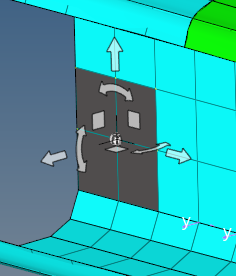
Use the Move Nodes panel to directly move specific nodes to new locations while morphing the surrounding mesh.
You can translate and rotate nodes, move nodes normal to a mesh, move nodes to a vector, node list, line, plane, surface, mesh, or equation, and apply a shape. For each morphing option, you can choose whether or not the morphing should be interactive. You can also control how those node movements apply to the surrounding mesh.
| Option | Action |
|---|---|
| edge bounding method | Available when you
morph nodes with selected fixed nodes and affected elements.
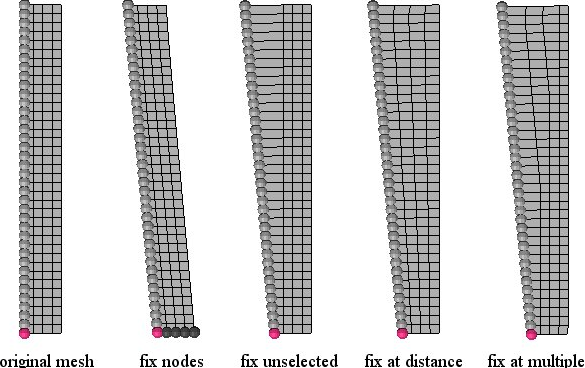
For options Morph All Nodes, Krig All Nodes, and Morph Within Envelope, the influence of the moving nodes extends beyond the mesh to which they are attached, thus you will need to fix or exclude any nodes that you do not want to have morphed. If you wish to exclude the nodes which are not displayed, set the selector below the fixed nodes selector to exclude undisplayed. Excluded nodes will neither be morphed nor will they affect the morphing. If you wish the nodes which are not displayed to act like fixed nodes, set the selector below the fixed nodes selector to fix undisplayed. Fixed nodes will influence the morphing by reducing the amount of morphing of any nearby nodes. If the selector is set to morph undisplayed, HyperMorph will morph any undisplayed nodes which are not fixed. Figure 1
shows how the different methods affect the mesh morphing using the move nodes tool.
For the partitioned option, the inner edge closest to the moved nodes is unaffected
since an edge domain is internally created for it. For the inferred edges option, no
inner edges were created and thus the inner edge ends up curved as its nodes follow
the moving nodes. For the free edges option, no outer edges were created either and
thus the outer edges end up curved as well as the inner ones. For the morph all
nodes and krig all nodes options, note the differences in the methods, especially
the smoothness of the kriging algorithm. For the morph within envelope option, note
how the mesh inside the envelope is linearly perturbed relative to the distance from
the moving node and that no fixed nodes are required.
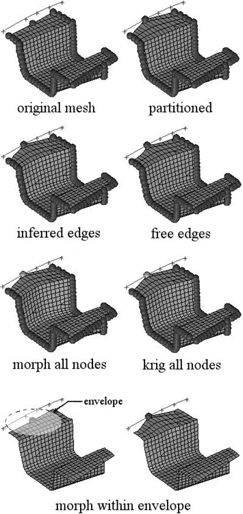 Figure 1. Example: Edge Bounding |
| movement direction | Choose the direction
that the affected nodes are projected.
Note: Available during any "move to" type of
morph.
|
| movement type | Choose the type of
movement.
|
| affected elements | When you perform any freehand morph with some fixed nodes defined, use this collector to select affected elements. The affected elements will morph to accommodate the movements of the moving nodes and the bounds imposed by the fixed nodes. The scope of their deformation is influenced by the edge bounding method chosen, the mv bias, and the fx bias. If you are using the morph all nodes, krig all nodes, or morph within envelope options, you do not need to select affected elements. |
| at origin / at system / at node | When using move to
equation, tchoose the start point for the function.
|
| calculate using: all elements / elems | When using move normal, choose to use either all elements when calculating the normal direction or to use only the elements you select. |
| calculate using: averaged norms / smoothed norms/ cfd corners | When using move
normal, choose how the normal direction is determined.
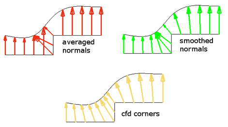 Figure 3. Example: Calculate Using Methods |
| deg | When you rotate, specify the desired number of degrees to rotate the moving nodes into this numeric box. |
| dist= | When you select fix at distance, specify the distance between the edge of the envelope and the moving nodes. Only nodes within the envelope will get morphed. |
| dist /
X/Y/Z/syst |
When you translate or move normal, choose to define either the distance to translate (in model units) with the direction defined by the along plane & vector selector, or to specify the distance and direction via X, Y, and Z components (and optionally, a local coordinate system for the components. |
| extend edges | Extend the edges of
the surfaces or mesh in a direction perpendicular to the normal
at the closest point on the surfaces or mesh. If this checkbox
is selected, the moving nodes will be projected on to an
extended representation of the surfaces or mesh, enabling you to
project nodes beyond the edge of the surfaces or mesh as well as
within any holes. If this checkbox is not selected, the moving
nodes will be projected on to the interior or edges of the
surfaces or mesh, which may end up distorting the morphed mesh.
In Figure 4, three surfaces are floating
above an angled mesh. All of the nodes of the mesh are
selected as moving nodes and they are projected to the
surfaces in the normal to geom direction. With extend edges
selected, the moving nodes are moved either to the surfaces
or to virtual surfaces which extend perpendicular to the
normal direction at the edge of the surface. Note how the
nodes end up placed inside the hole in the center of the
largest surface. Without extend edges selected, the moving
nodes are moved to the nearest point of the surfaces. Note
how several layers of moving nodes end up compressed at the
edge of the surfaces and around the edge of the hole.
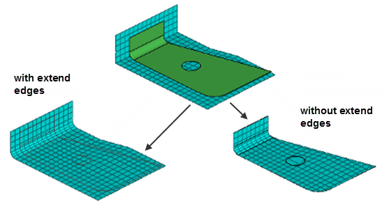 Figure 4. Note: Available when using move to surf or move to
mesh.
|
| fixed nodes / fix unselected / fix ast distance / fix at multiple: |
|
| fx bias | This numeric box displays when you morph nodes with selected fixed nodes. It affects the behavior of the nodes to be morphed. Higher values keep morphed nodes closer to the fixed nodes, reducing local distortion. |
| interactive: on/off | Drag handles across
the screen using the mouse after clicking morph. Morphing occurs
in real time, rather than in a single "jump" based on input
distances or angles upon clicking the button. Note: When morphing by a manipulator all morphing is done
interactively.
|
| moving nodes: | Pick the nodes that
will move. When using apply shape, this collector is replaced by a shape collector to allow you to pick an existing shape. |
| mult | When morphing by apply shape, apply a multiplier to the effect of the shape. The default value of 1 uses the shape at its default size/strength, while higher numbers increase its effect on nodes and decimal values between zero and one decrease its effect. |
| mult= | When you select fix at multiple, specify the distance between the edge of the envelope and the moving nodes. Only nodes within the envelope will get morphed. |
| mv bias |
Affects the behavior of morphed nodes. Higher values result in
morphed nodes following the moving nodes more closely, reducing local
distortion.
Note: Available when you morph nodes with selected fixed
nodes.
|
| node a, node b | The target is defined
as the vector from node a to node b. Note: Available when the
movement type is set to move to vector.
|
| offset= | When moving nodes to a
vector, node list, line, plane, surface, or mesh you have the
option of setting how far the nodes will be offset from the
target. Although the nodes will be moved in the specified
projection direction, the offset will be the absolute distance,
in model units, the nodes will end up from the target regardless
of the direction in which they were moved. A positive value for the offset will place the nodes short of the target, a negative value for the offset will place the nodes beyond the target, and an offset of zero will place the nodes on the target. |
| offset in all dir. / offset along proj. | When moving nodes to a
vector, node list, line, plane, surface, or mesh while using a
non-zero offset, choose an offset method.
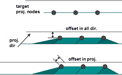 Figure 6. Example: Offset in All Dir. and Offset in Proj. |
| optional fixed nodes | Add any fixed nodes inside the envelope to be used for morphing. The morphing of any nodes near these fixed nodes will be reduced. |
| options | Opens the Morph Options panel. |
| rotate about | Use the standard plane & vector selector to define an axis around which to rotate the moving nodes. |
Record Subpanel
Use the Record subpanel to record the movement of nodes applied in other panels and save those movements as a morph that can be undone, redone, and saved as a shape.
You can then go outside of the Freehand panel and use any tool in Engineering Solutions to move the nodes in the model to new positions. When you return to this panel and click finish, those node movements will be transformed into a morph which can be undone, redone, or saved as a shape.
This feature can be particularly useful when using the Quality Index panel to adjust a basic morph for the sake of mesh quality. For example, after morphing, go to the Record subpanel and click start, go to the Quality Index panel to adjust and fix any poorly-formed elements resulting from the morph, and then return to the Record panel and click finish.
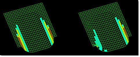
Figure 7.
| Option | Action |
|---|---|
| edge bounding |
For options Morph All Nodes, Krig All Nodes, and Morph Within Envelope, the influence of the moving nodes extends beyond the mesh to which they are attached, thus you will need to fix or exclude any nodes that you do not want to have morphed. If you wish to exclude the nodes which are not displayed, set the selector below the fixed nodes selector to exclude undisplayed. Excluded nodes will neither be morphed nor will they affect the morphing. If you wish the nodes which are not displayed to act like fixed nodes, set the selector below the fixed nodes selector to fix undisplayed. Fixed nodes will influence the morphing by reducing the amount of morphing of any nearby nodes. If the selector is set to morph undisplayed, HyperMorph will morph any undisplayed nodes which are not fixed. Figure 1
shows how the different methods affect the mesh morphing using the move nodes tool.
For the partitioned option, the inner edge closest to the moved nodes is unaffected
since an edge domain is internally created for it. For the inferred edges option, no
inner edges were created and thus the inner edge ends up curved as its nodes follow
the moving nodes. For the free edges option, no outer edges were created either and
thus the outer edges end up curved as well as the inner ones. For the morph all
nodes and krig all nodes options, note the differences in the methods, especially
the smoothness of the kriging algorithm. For the morph within envelope option, note
how the mesh inside the envelope is linearly perturbed relative to the distance from
the moving node and that no fixed nodes are required.
Figure 8. Example: Edge Bounding Note: Available when you apply and morph the moved nodes.
|
| affected elements | The affected elements will morph to accommodate the movements of the moving nodes and the bounds imposed by the fixed nodes. The scope of their deformation is influenced by the edge bounding method chosen, the mv bias, and the fx bias. If you are using the morph all nodes, krig all nodes, or morph within envelope options, you do not need to select affected elements. |
| fixed nodes / fix unselected / fix at distance / fix at multiple |
|
| fx bias | This numeric box displays when you morph nodes with selected fixed nodes. It affects the behavior of the nodes to be morphed. Higher values keep morphed nodes closer to the fixed nodes, reducing local distortion. |
| moved nodes: apply / apply and morph | In Figure 10, the record feature is used to record a single
node on the right side of the mesh being moved using the
Distance panel. The middle image uses apply; the right image
uses apply and morph with the corner nodes selected as fixed,
and all elements selected as affected elements, so the whole
mesh stretches.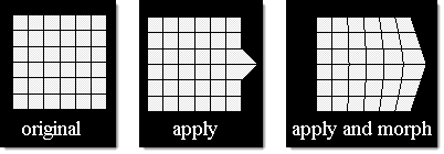 Figure 10. |
| mv bias | Affects the behavior
of follower nodes. Higher values result in stretched or "follower" nodes following the moving nodes more closely. Note: Available when you morph nodes with
selected fixed nodes and affected elements.
|
| options | Opens the Morph Options panel. |
Sculpting Subpanel
Use the Sculpting subpanel to mold a mesh with a variety of virtual tools, such as creating hemispherical divots, cone-shaped projections, or molding sections with feature lines.
Areas of the mesh can be pushed or pulled to reshape it, creating either indentations or projections on the mesh.
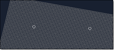
Figure 11. Two Nodes Selected, Tool not Applied
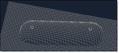
Figure 12. Ball Tool Applied to the Mesh. The ball tool has been applied to the mesh as if it had been rolled from one node to the other.
| Option | Action |
|---|---|
| affected elements | Select the elements you wish to be subject to the sculpting. In this way, you can preserve parts of the mesh during sculpting (by simply not picking them). |
| angle = | When sculpting with the cone tool, specify the angle of the cone's taper. |
| base | The base node serves
as a "handle" for the tool. The base node is moved along the
path and the tool moves relative to the base
node. Note: Available for node list, line, surface, or
mesh.
|
| mesh compression |
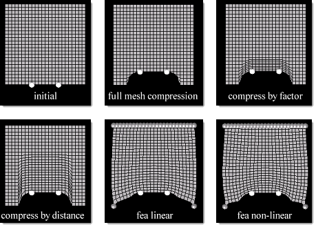 Figure 13. |
| move direction | Define the direction that nodes are moved when sculpted. The two options are to use a standard plane and vector selector to define a vector, or to sculpt in the mesh element's normal direction. |
| offset = | Specify the offset to determine how far the tool will be offset from the path in the move direction. |
| options | Opens the Morph Options panel. |
| radius = | When sculpting with the ball or cylinder tool, specify the size of the tool. |
| sculpting tool | Choose the basic shape
that will be used for sculpting. When sculpting with a cylinder or plane, a new (unlabeled) plane and vector selector displays under the tool label. Use this (including a base node) to define the cylinder's axis, or the plane tool itself. 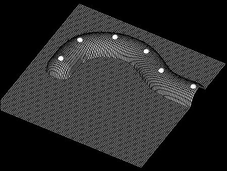 Figure 14. Ball. The ball tool has been applied to a node list. 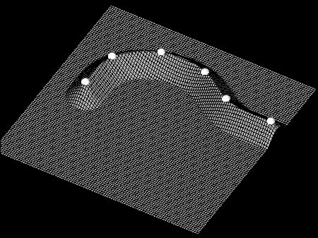 Figure 15. Cone. The cone tool has been applied to a node list with an offset. The tip of the cone is moved along the node list, which, if the node list was selected along the mesh to be sculpted, will not result in any morphing. Use an offset to push the cone past the surface of the mesh as shown in the example. 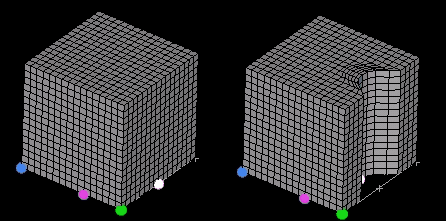 Figure 16. Cylinder. A cube has been sculpted with a cylinder tool at a single point. Notice the mesh compression extending into the body of the mesh 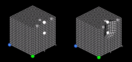 Figure 17. Node List. A cube has been sculpting with a node list (gray circles) along a path (white circles). 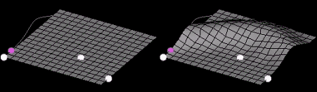 Figure 18. Line. A line tool is used to sculpt a mesh. Notice how the base point (purple circle) is used to locate the line relative to the path (white circles). 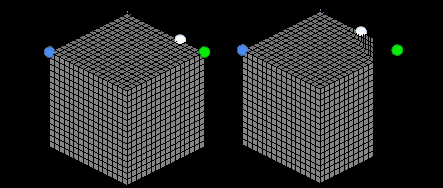 Figure 19. Plane. A plane tool is used to sculpt a solid cube. A single node is used for the path and mesh compression of 0.5 is selected. Notice that the sculpt direction is different from the plane normal. 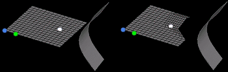 Figure 20. Surface. A surface is used to sculpt a mesh. A single node is used for the path (which ends up getting morphed due to the mesh compression). Notice the effect of the taper angle (45 degrees) on either side of the tool and how it prevents large mesh distortions at the tool edge. 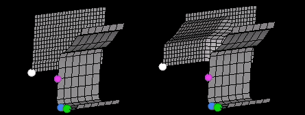 Figure 21. Mesh. A mesh tool is used to sculpt another mesh. Since the path lies on the target mesh and the base node is at the leading face of the tool, an offset was used to create the sculpting. |
| taper angle = | When sculpting with a
node list, line, surface, or mesh tool, specify a taper angle
for the tool to alter the taper of the resulting deformation.
The taper of the tool is like a shroud around the tool extending opposite of the sculpt direction, at the given angle. For instance, the taper for a point is a cone. The taper helps to smooth transitions between sculpted and non-sculpted regions. |
| tool path | Choose the path along
which the tool will be moved; the center of the tool follows the
path.
|
Save Shape Subpanel
| Option | Action |
|---|---|
| as handle perturbations / as node perturbations | Shapes saved as handle perturbations take up less space and can change if the domains and handles for the model are changed. If you edit the domains and handles in a model that has saved shapes or morphs on the undo/redo list, you will be given the option to preserve those shapes as node perturbations. If you click yes, the shapes will retain their original form. If you click no, the shapes will be unchanged internally, but may be appear different due to changes in the influences of the perturbed handles. |
| color | Select a color for the current shape. |
| name = | Specify a name for a new shape, or click the button twice to select an existing shape. |
Command Buttons
| Button | Action |
|---|---|
| finish | Stop morphing macro recording. |
| morph | Perform the morphing (move nodes). |
| move + | Sculpt in the positive
direction relative to the move direction input.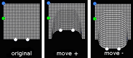 Figure 22. |
| move - | Sculpt in the negative direction relative to the move direction input. |
| redo | Redo the last morphing action. |
| redo all | Redo all recent morphing actions. |
| save | Save the current shape. |
| start | Begin recording a complex morph macro. |
| undo | Undo the last morphing action. |
| undo all | Undo all recent morphing actions. |