Automeshing Secondary Panel
Use the Automeshing Secondary panel to create meshes interactively on surfaces, or create meshes without a surface present.
Location: The Automeshing Secondary panel serves as the unified secondary panel for most of the plate and shell meshing panels; using those panels gives you access to this Automeshing Secondary panel. In the Automeshing Secondary panel you can interactively adjust a wide variety of parameters and choose from a suite of algorithms. Engineering Solutions responds with immediate feedback on the effects of the changes, until you are satisfied with the resulting mesh.
- If you use surfaces, you may choose from a greater variety of algorithms, have more flexibility in specifying the algorithm parameters, and employ the mesh-smoothing operation to improve element quality.
- If you do not use surfaces, the meshing process is usually faster and uses less memory. Most of the functions are still available and operate in the same way. Furthermore, there are situations in which it is not possible or not desirable to create a surface.
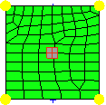
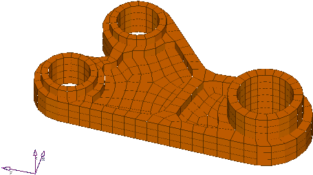 Figure 1. Solid Model Created by Dragging Automeshed Plate Elements |
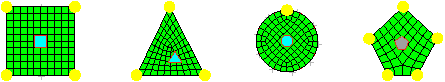
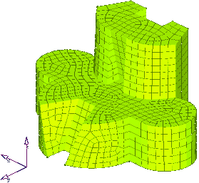 Figure 2. Second Order Elements Created for Boundary Element Solutions |
The Automeshing Secondary panel shows the pre-generated mesh from its preceding Automesh subpanel, and provides tools to adjust the mesh before finalizing it.
While you are using the Automeshing Secondary panel, the function keys are disabled and you cannot change the element order on the Options panel.
As a secondary panel dependent on the subpanel that activates it, the changes you make are only applicable to the current meshing action. Leaving the secondary panel will render its settings irrelevant since the only means of return is to restart meshing from one of the Automesh subpanels.
- Set the secondary panel mode by selecting the appropriate subpanel.
- Use the criteria presented by the subpanel to alter the final mesh outcome.
- Click mesh to finalize the mesh, reject to abort, or smooth to automatically improve the mesh quality.
Density Subpanel
| Option | Action |
|---|---|
| adjust: edge | Change the number of nodes along an edge. When this
selector is enabled:
|
| calculate: edge | Calculate edge density to support the specified element
size. When this selector is enabled, click an edge to set the necessary density to support the specified element size. |
| calculate: recalc all | Set all edges to the number of nodes necessary to support the specified element size. |
| elem size= | Specify the desired element size for edges. Use calculate:
edge or calculate: recalc all to set edges to the necessary
nodal density to support this element size as well as
possible.
Note: This will be a "best fit" calculation, as
it is unlikely that the selected edge will be exactly
the right length for the specified element
size.
|
| link opposite edges | Changes applied to one linked edge will be applied to the opposite edge of simple chains when edges are clicked. |
| set: edge | Set an edge's nodal density to the value specified in the
elem density field. When this selector is enabled, click an edge to set its nodal density. |
| set: set to all | Set all edges to the nodal density specified in the elem density field. |
| elem density | Specify a required number of elements to lie on the edge, producing a number of nodes one greater than this value. |
| local view | Open the Local View menu to access display tools that are customized for use in the Automeshing Secondary panel. |
Mesh Style Subpanel
| Option | Action | |||||||||
|---|---|---|---|---|---|---|---|---|---|---|
| elem type | Change the element type assigned to the selected surface(s).
|
|||||||||
| mesh method | Change the mesh mapping method assigned to the selected
surface(s).
|
|||||||||
| set |
|
|||||||||
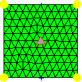
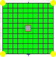
| flow: align |
Produce a more orthogonal quad-dominant mesh.
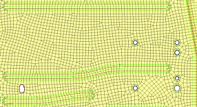 Figure 12. No Flow Alignment 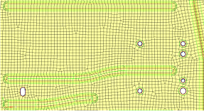 Figure 13. Flow Alignment. Flow alignment is used, producing straighter rows of elements. |
|||||||||
| flow: size |
Enforces a global mesh element size with minimal min/max
element size variation.
Important: Only available when flow: align is
selected.
|
|||||||||
| map: size | Keep the elements roughly the same size. | |||||||||
| map: skew | Prevent the mesh from producing highly-skewed elements. | |||||||||
| map: smoothing | Perform an automatic cleanup pass on the generated mesh in an effort to improve the overall element quality. | |||||||||
| local view | Open the Local View menu to access display tools that are customized for use in the Automeshing Secondary panel. |
Biasing Subpanel
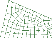
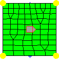
Figure 14. Mesh Generated without Element Biasing. The poor aspect ratios of the elements in the lower right-hand corner.
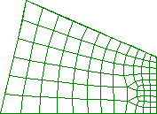
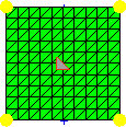
Figure 15. Mesh Generated with Element Biasing. Biasing the elements along the top and bottom edges improves angles and aspect ratios.
| Option | Action |
|---|---|
| adjust: edge | Change the biasing factor for an edge. When this selector
is enabled:
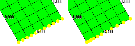 Figure 16. Increase Biasing Factor |
| calculate: edge | Set an edge's biasing factor to the specified intensity value by enabling the selector and clicking an edge. |
| revert: edge | Revert an edge in the opposite direction by enabling the selector and clicking the edge. |
| recalc all | Set all edge's biasing factor to the specified intensity value. |
| intensity= | Specify a biasing factor. This value will be applied to the edge(s) selected using the calculate: edge or recalc all options. |
| link opposite edges | Changes applied to one linked edge will be applied to the opposite edge of simple chains when edges are clicked. |
| set |
|
| bias style | Select the biasing style to apply to edges when using the set
edge and set all to options.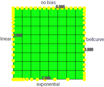 Figure 17. Example: Bias Style |
| local view | Open the Local View menu to access display tools that are customized for use in the Automeshing Secondary panel. |


Checks Subpanel
Use the Checks subpanel to use the functions of the Check Elements panel on a newly-generated mesh before storing it in the database. The tests are the same as on the Check Elements panel, and elements that fail a quality test are highlighted in red. Only displayed elements are tested; the display of elements is controlled by the local view panel. The Checks subpanel operates on a by-face method. The active highlighted face serves as a frame of reference for meshing, smoothing, and display operations. To select another face, select the face's icon in the modeling window.
In this subpanel, you can specify minimum or maximum values for element quality criteria according to several measures. The final mesh will attempt to adhere to the requirements set on this panel by producing elements that do not violate these quality criteria.
The criteria includes warpage, aspect, skew, min angle and max angle (quads only), length, jacobian, and min angle/max angle (trias only).
Open the Local View menu to access display tools that are customized for use in the Automeshing Secondary panel.
Local View Menu
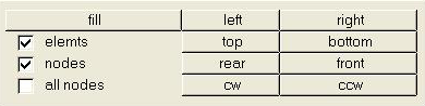
Figure 18. Local View Menu - Regular Version
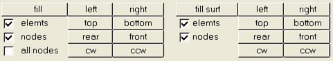
Figure 19. Local View Menu - Expanded Version
- cw, ccw
- Rotate the view clockwise or counterclockwise around the center of the surface, ignoring everything else in the Engineering Solutions database.
- left, right, top, bottom, rear, front
- Set the view to look from that direction, and then fills the screen with the surface.
- fill surf
- Size the selected surface(s) to fill the modeling window.
- elemts, nodes, all nodes
- Control the display of elements and nodes.
- The ability to hide elements of other faces is particularly useful when you have a complicated surface with several faces and the some surfaces are interfering with your view.
- It can be helpful to display all of the elements of the other faces and hide those of one face. In this way, you can look inside a complicated object.
Command Buttons
| Button | Action |
|---|---|
| mesh | Scan through all of the faces in the current frame of reference for ones that have not yet been meshed or have a mesh that is out of date with respect to the user-specified parameters, and then attempt to bring them up to date. If the current subpanel is density, mesh style, type, or biasing, the current frame of reference is the entire surface. If the current subpanel is details or checks, the current frame of reference is the highlighted face. |
| reject | Discard a generated mesh of one selected face or of all of the faces of the current domain. |
| smooth | Apply a mesh smoothing algorithm to each face in the current frame of reference. |
| undo | Return the nodes on the mesh to the positions they were in before the last time you applied a smooth to that mesh for each face in the current frame of reference. |
| abort | Exit the Automeshing Secondary panel without saving any elements or nodes to the database. If the module was entered from a surface creation panel, any surface that may have been created is discarded. |
| return | Exit the Automeshing Secondary panel, and save elements or nodes to the database. |