Solid Map Panel
Use the Solid Map panel to create a mesh of solid elements in a solid geometric volume.
Location: 3D page
Only relatively simple solids can be meshed; complex objects must first be partitioned into simpler sections so that the sections can be meshed individually.
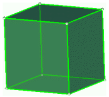
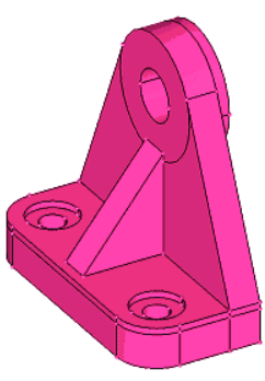
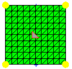
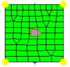
- Blue
- A solid that has not been edited at all, and therefore is not evaluated for mappability.
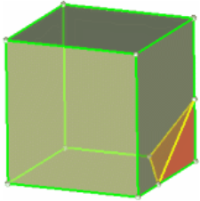
- Orange
- A solid that has been edited, but remains completely unmappable (further partitioning may enable mapping).
- Yellow
- A solid that is mappable in one direction.
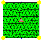
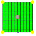
- Green
- A solid that is mappable in three directions (this is very rare).
 |
 |
You can omit the source, the destination, or the along geometry by setting either one of the entity selectors to (none). Only one of these selections can be set to (none); the other two selections are then required to define the volume to fill.
The 2D meshes extruded do not have to be continuous.
The "along" faces do not all have to be defined.
You can create elements with a user-specified bias by selecting linear, exponential, or bellcurve after bias style. Specify the bias intensity value after intensity = and click mesh.
General Subpanel
Figure 2.
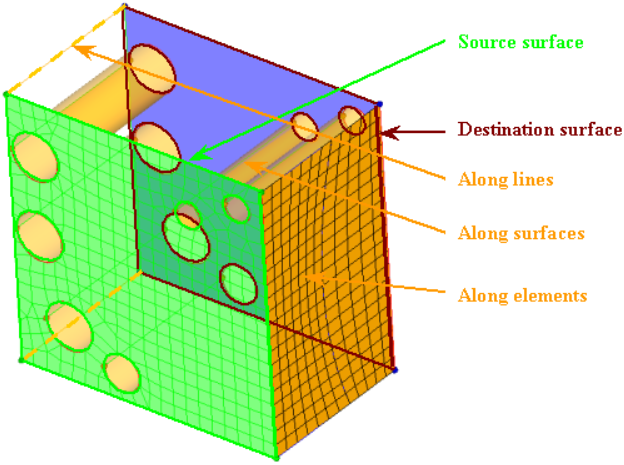
Figure 3.
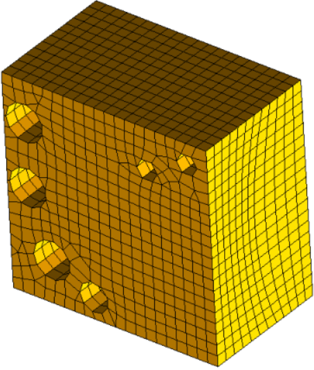
Figure 4.
| Option | Action |
|---|---|
| source geom |
Choose a method for selecting source geometry that defines
the source face of the 3D volume.
|
| elems to drag | Select the elements/mesh that correspond to the source face extruded to create the solid mesh. If the source face type chosen is a surface, the elements to drag selection is optional as the elements associated to the surface are automatically selected. |
| dest geom |
Choose a method for selecting the geometry that defines the
destination face of the 3D volume.
|
| elems to match / smooth dest |
|
| along parameters | Define/set the parameters required for the mesh along the solid map. Set the element size or density (toggle) to be defined in the along direction. This determines the number of elements along the depth of the mapping. If the size or density is set to "0", the element size/density is calculated based on the average element size of the source elements (elems to drag). |
| along bias style | Choose the type of biasing to use while creating nodes in the along direction. The biasing style works in conjunction with biasing intensity. If intensity is set to "0" the biasing is not applied. |
| intensity | Specify the biasing intensity value. |
| 3d elem faces by nodes | Select 3d elements faces by nodes as input. |
| apply orthogonality to along | Keep the solid elements generated more perpendicular to the surface faces in the along direction. |
Line Drag Subpanel
| Option | Action |
|---|---|
| elems to drag | Select the elements/mesh that correspond to the source face extruded to create the solid mesh. If the source face type chosen is a surface, the elements to drag selection is optional as the elements associated to the surface are automatically selected. |
| elems to match / smooth dest |
|
| along geom |
Choose a method for selecting the geometry that defines the
face of the 3D volume along which you wish to map the mesh.
|
| along parameters | Define/set the parameters required for the mesh along the solid map. Set the element size or density (toggle) to be defined in the along direction. This determines the number of elements along the depth of the mapping. If the size or density is set to "0", the element size/density is calculated based on the average element size of the source elements (elems to drag). |
| along bias style | Choose the type of biasing to use while creating nodes in the along direction. The biasing style works in conjunction with biasing intensity. If intensity is set to "0" the biasing is not applied. |
| intensity | Specify the biasing intensity value. |
Linear Solid Subpanel
| Option | Action |
|---|---|
| elems to drag | Select the elements/mesh that correspond to the source face extruded to create the solid mesh. If the source face type chosen is a surface, the elements to drag selection is optional as the elements associated to the surface are automatically selected. |
| elems to match | Select the elements on the destination surface that you wish the 3D mesh to match up with. |
| along geom | Choose a method for
selecting the geometry that defines the face of the 3D volume
along which you wish to map the mesh.
|
| along parameters | Define/set the parameters required for the mesh along the solid map. Set the element size or density (toggle) to be defined in the along direction. This determines the number of elements along the depth of the mapping. If the size or density is set to "0", the element size/density is calculated based on the average element size of the source elements (elems to drag). |
| along bias style | Choose the type of biasing to use while creating nodes in the along direction. The biasing style works in conjunction with biasing intensity. If intensity is set to "0" the biasing is not applied. |
| intensity | Specify the biasing intensity value. |
Ends Only Subpanel
| Option | Action |
|---|---|
| source geom |
Choose a method for selecting source geometry that defines
the source face of the 3D volume.
|
| dest geom |
Choose a method for selecting the geometry that defines the
destination face of the 3D volume.
|
| elems to drag | Select the elements/mesh that correspond to the source face extruded to create the solid mesh. If the source face type chosen is a surface, the elements to drag selection is optional as the elements associated to the surface are automatically selected. |
| elems to match / smooth dest |
|
| along parameters | Define/set the parameters required for the mesh along the solid map. Set the element size or density (toggle) to be defined in the along direction. This determines the number of elements along the depth of the mapping. If the size or density is set to "0", the element size/density is calculated based on the average element size of the source elements (elems to drag). |
| along bias style | Choose the type of biasing to use while creating nodes in the along direction. The biasing style works in conjunction with biasing intensity. If intensity is set to "0" the biasing is not applied. |
| intensity | Specify the biasing intensity value. |
One Volume Subpanel
| Option | Action |
|---|---|
| volume to mesh | Select the solid to mesh. |
| source hint | Select the "beginning" surface that defines the direction of mesh mapping. |
| dest hint | Select the "ending" surface that defines the direction of mesh mapping. |
| source shells |
Select the type of source shells that define the 2D mesh
on the initial surface of the solid, and will dictate the output element type when
meshing the solids.
|
| along geom |
Choose a method for selecting the geometry that defines the
face of the 3D volume along which you wish to map the mesh.
|
| along parameters | Define/set the parameters required for the mesh along the solid map. Set the element size or density (toggle) to be defined in the along direction. This determines the number of elements along the depth of the mapping. If the size or density is set to "0", the element size/density is calculated based on the average element size of the source elements (elems to drag). |
| along bias style | Choose the type of biasing to use while creating nodes in the along direction. The biasing style works in conjunction with biasing intensity. If intensity is set to "0" the biasing is not applied. |
| intensity | Specify the biasing intensity value. |
| smooth dest | Smooth the elements on the resulting face of the solid to improve the resulting mesh quality. |
| elems to solid/surf comp / elems to current comp |
Select which component to put the
newly-created elements.
|
Multi Solids Subpanel
Use the Multi Solids subpanel to select multiple mappable solids and create 3D meshes for them.
This does not always work for large numbers of solids, even if they are all mappable. In some cases you may need to mesh them a few at a time or even (in extreme cases) individually.
 |
 |
| Option | Action |
|---|---|
| solid | Select the desired
solids. Note: Only solids that are mappable can be
meshed.
|
| check geom | Checks selected solids for any topological issues. Tiny edges will be colored pink and twisted edges will be colored red. |
| interactive / automatic |
|
| elem size | Specify the size to when initially distributing the nodes to the edges. |
| source shells |
Select the type of source shells that define the 2D mesh
on the initial surface of the solid, and will dictate the output element type when
meshing the solids.
|
| source hint | Select the "beginning" surface that defines the direction of mesh mapping. |
| dest hint | Select the "ending" surface that defines the direction of mesh mapping. |
| elems to solid/surf comp / elems to current comp |
Select which component to put the
newly-created elements.
|
| smooth dest | Smooth the elements on the resulting face of the solid to improve the resulting mesh quality. |
| stop meshing on bad jacobian | Halt the meshing routines upon the creation of a bad jacobian solid element. |
| previous settings | When creating the temporary surface mesh, honor any prior edge node density settings. |
| keep 2d mesh | Keep any surface mesh associated to selected solids/surfaces. |
Thin Solids Subpanel
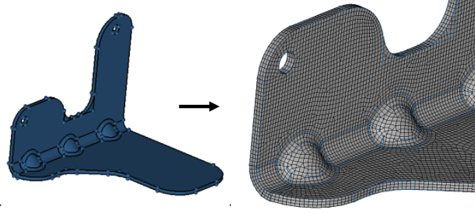
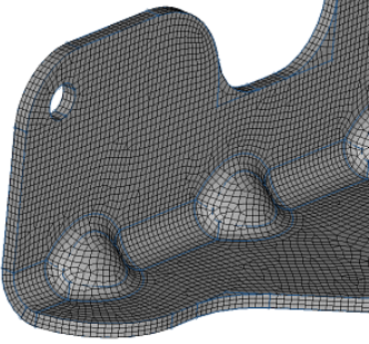
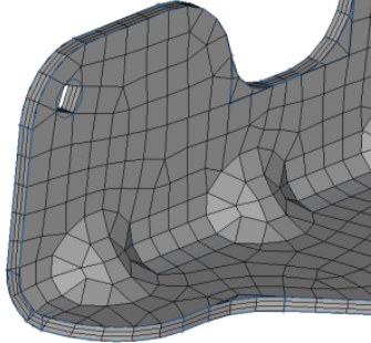
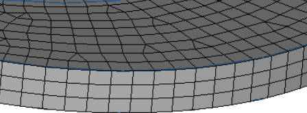
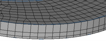
Figure 6. Thin Solids. The first image displays geometry that represents thin, bent sheet metal. The second image displays the mesh, which consists of three layers and mixed element type.
- The solid entity should be a bent sheet metal solid.
- You should be able to identify both the Source (start) faces and the Destination faces.
- Source and destination faces must be connected by side (along) faces which are almost 90 degrees to them.
- The number of top and bottom faces do not need to match.
- Side faces do not need to be four-sided.
| Option | Action | ||||
|---|---|---|---|---|---|
| thin solid mesh | Select whether to mesh elements or solids. | ||||
| along surfs/source surfs (may hint) | Select surfaces that define the source face of the thin solid. A single surface selection as hint will work. | ||||
| destination (may hint) | Select surfaces that define the destination face of the thin solid. A single surface selection as hint will work. | ||||
| save src to SAVELIST | On detect, will save source surfaces to mark. This can be retrieved in other surface selection panels. | ||||
| number of layers: | Specify the number of layers of elements to build along the normal direction. | ||||
| element size = / elem_size/thickness |
|
||||
| element type = | Select the type of
elements used in the initial shell mesh from which solid
elements are created.
|
||||
| linear or no biasing / exponential biasing /bellcurve biasing | Select the biasing
affects element growth in successive layers, moving away from
the source faces.
|
||||
| bias intensity = | Specify the biasing intensity value.This numeric value affects how strongly the biasing effect is. When left at zero, no biasing is applied. | ||||
| elements to current comp / original comp | Choose whether to organize the newly created components in the current component, or in the components of the shell elements. | ||||
| post cleanup elems | Choose whether to optimize the generated hex mesh. If checked, optimization is performed to improve Jacobian and warpage quality. Avoids negative Jaobian elements created using thin solid. |
Command Buttons
| Option | Action |
|---|---|
| mesh | Create a solid mesh with all the provided input. The solid mesh created is placed in a collector named solidmap. If that collector does not exist, a new component is created with that name. |
| reject | Reject the last mapped solid mesh created. |
| equiv/faces | Equivalence all of the elements in the solidmap component and create the faces (^faces component) for that component. This function is optional and does not directly impact the solidmap functionality. It allows you to perform faster and easier solid modeling. The solidmap component is equivalenced with an initial tolerance of 1% of element size. When this function is performed, a message is displayed informing you of the number of nodes equivalenced along with the tolerance value used. Any subsequent use of this function without performing additional solid mapping increases the tolerance (to a maximum of 10% element size) before equivalencing again. |
| return | Exit the panel. |