Morph Options Panel
Use the Morph Options panel to access options that are common to many of the other HyperMorph panels, and which affect morphing behavior. Morph options determine both the algorithms used for morphing as well as how the morph is carried out by controlling features like symmetries, morph constraints, automatic smoothing and automatic element quality checks.
Location: Tools page > HyperMorph module
The Morph Options panel contains subpanels for morphing options, auto qa options, domain solvers, global options, fea results, and parameters.
Changes made on one subpanel do not affect the others, and are persistent so that you can switch freely between subpanels without losing any settings already made.
Morphing Subpanel
| Option | Action |
|---|---|
| second-order element handling | Choose a method for
handling second order element mid-nodes.
|
| active constraints | Select which
constraints will be active. Active morph constraints influence morphing operations, while inactive morph constraints do not. All currently active morph constraints are automatically loaded into the selector when you enter the panel. To deactivate all of the active constraints, click reset on the constraint selector. |
| active symmetries | Select which
symmetries will be active. Note: Changing the
active status for any non-reflective symmetry will trigger
the recalculation of influences for the affected domains
once you leave the Morph Options panel.
Active symmetries will influence morphing operations while inactive symmetries will not. All currently active symmetries are automatically loaded into the selector when you enter the panel. To deactivate all of the active symmetries, click reset on the symmetry selector. |
| minimum step size | Specify the minimum step size used during interactive morphing. All morphing applied using interactive methods, such as using a manipulator, dragging a handle along a vector, or dragging a handle across a surface, will be rounded to the nearest multiple of the minimum step size before being applied to the handles. Thus, setting the minimum step size distance to 1.0 will force the handle to be morphed in steps no less than 1.0, such as 2.0, 3.0, 6.0 and so on. These steps will be reflected in the movement of the handles across the screen, which will occur in discrete increments. The distance field applies to translations and is given in model units. The angle field applies to rotations and is given in degrees. |
| mvols: active / inactive / skin only | Active morph volumes
will morph any nodes registered to them when morph volume
handles are moved. Inactive morph volumes will not move any
registered nodes. By setting the morph volumes to be inactive
you can use the morph panel to modify the positions of your
morph volumes without affecting the mesh. When morph volumes are
reactivated by changing the selector to mvols:active or
mvols:skin only, HyperMorph
re-registers the registered nodes. During this process,
registered nodes may end up registered to different morph
volumes or to no morph volume, but unregistered nodes will not
get registered to the morph volumes even though they may now
reside inside the morph volumes after morphing. If you need to
register these nodes for your morph volumes, you can do so in
the update mvols subpanel of the Morph Volumes panel. The
mvols:skin only feature delays the morphing of any nodes
inside of a solid mesh until the solve button is clicked.
This allows you to more rapidly morph your model if it
contains a large number of nodes, while still being able to
see what effects your morphing is having on the model. To
use this feature, switch the selector to mvols:skin only,
make any number of shape changes to your morph volumes, and
then click the solve button to morph the interior
nodes.
Note: Switching the selector away from
mvols:skin only will automatically trigger the morphing
of the nodes inside the solid mesh.
|
| symlinks | Create links between
symmetric handles active or inactive for all symmetries. When unchecked, morphing the model behaves differently. Reflective symmetries (1-plane, 2-plane, 3-plane, and cyclical) are completely ignored, while non-reflective symmetries no longer link handles but still affect node influences. Select symlinks to reactivate them for subsequent morphs in which you need symmetry. |
| use constraints | Turn your constraints
on and off without changing their active status. If unchecked, constraints will not be applied to the model while morphing. If checked, only the active constraints will be applied during morphing. This allows you to perform some morphing options without using any constraints, and then reactivate the constraints for further morphing. |
Auto QA Subpanel
| Option | Action |
|---|---|
| auto quality check | Evaluate element
quality after every morphing operation, including the
application of constraints when they are created. HyperMorph will run the element check in
either the standard mode, which will highlight failed elements,
or in color plotting mode, which will show the element check
results for each element with colors that reflect the element's
quality, and give a brief report in the message bar. On screen
the letters QA will appear and you may either left-click to
refresh the screen and continue morphing, or right-click to save
the elements to the user mark. In interactive mode the
highlighting or color plotting will occur in real time. A wide
variety of checks are available for 1D, 2D, and 3D checks
including warpage, minimum length, Jacobian, and more. In
addition, the extended entity selection menu includes an off
option to completely forgo automatic quality checking. You may also choose to turn off negative jacobian checking in this panel by unchecking the check neg. jacobians checkbox. Whenever a morphing operation is performed, HyperMorph will check the model for elements with negative jacobians. If one or more elements with a negative jacobian are found, an error will be reported and Engineering Solutions will be paused until you click the mouse button. If you do not want this check to occur, such as if you are running a batch script, you can turn the check off. |
| auto remeshing | For both manual and on
release remeshing, select the mesh style (quads, trias, mixed,
or right trias), the target element size, and whether you want
size control, skew control, to preserve shapes, and whether or
not to also remesh 3D elements. For automatic remeshing on
release, there is a text box labeled qa fail% >. This value
represents the percentage of affected elements that have to
fail the auto quality check before remeshing is
triggered.
Note: Automatic remeshing will not
be active unless automatic quality check is turned on,
as the automatic quality check is used to supply the
current qa fail%.
During automatic
remeshing (which is active when you select the on release
option), watch carefully as new messages are written to the
screen after morphing. After highlighting the elements which
failed the auto qa, if the number of failed elements exceeds
the qa fail %, you will see the message, "QA - right
click to remesh," instead of simply,
"QA" written either next to your cursor
or in the bottom-right corner of the window. If you
right-click, all affected domains and elements will be
remeshed. If you left-click, remeshing will not occur. Once
the remesh is complete, you will see the message,
"remesh - right click to reject." This is
your only chance to reject the remeshing that has been
performed. If you right-click, the remeshing will be
rejected and the morphing will be retained. If you
left-click, the remeshing cannot be undone, although the
morphing can be.
Note: An affected element is any
element that touches a node that has been morphed,
whether or not it has failed QA. An affected domain is
any domain that contains an affected
element.
|
| auto smoothing | Reduce mesh distortion
during a morphing operation, using the same methods as the
smooth panel. HyperMorph applies the
smoothing to all affected domains and all elements that contain
an affected node.
To control how smoothing is applied during interactive
morphing select either on release or real time. If you
select on release, the smoothing will not occur until you
release the mouse button. If you select real time, the
smoothing will occur as you are morphing.
Note: Smoothing in real time can be slow for large
meshes.
|
| check neg. jacobians | Check for Jacobian values that are negative. |
| color plotting | Draw in colors representing their quality status (good, pass, fail). |
Domain Solvers Subpanel
| Option | Action |
|---|---|
| kriging: | Choose when kriging is
performed for domains and morph volumes.
|
| max # elems | Specify the largest
number of elements for which the small domain solver will be
used. Note: Available when domain morphing is set to fea
linear or fea non-linear.
|
| min # elems | Morphing domains with
more elements than this value will invoke the Large Domain
Solver instead of using pre-calculated influence coefficients.
The Large Domain Solver is slower than using influence
coefficients for small domains, but is much faster at morphing
very large numbers of elements since solving for the influence
coefficients can be very time consuming for large domains. Note: After domain creation or editing, the influences
for large domains do not need to be solved which allows you
to work with much larger domains than in early versions of
HyperMorph.
|
| large domain morphing | Choose when to perform
the morphing of large domains.
If elements become folded during morphing, choose how to
trigger the automatic unfolding and optimization step.
Unfolding can be compute-intensive depending on the number
off elements involved.
|
| small domain morphing | Choose how the
morphing of small domains is performed.
For standard or kriging methods you may set autofix squashed domains to either off, on release, or real time. When set to on release or real time, this option will automatically try to unfold any domains which get folded during morphing. When set to on release the unfolding operation will occur after each morphing operation is applied but not during interactive morphing. When set to real time the unfolding operation will occur after each morphing operation is applied as well as during interactive morphing. For either fea linear or fea non-linear
morphing, additional options are available.
|
Global Subpanel
| Option | Action |
|---|---|
| 1D/conn /eq cluster rotation | Choose the rotation
applied to any connectors or equations treated as clusters, or
to cluster domains.
|
| connector/cluster /eq morphing | Choose how connectors,
cluster domains, and equations are treated.
|
| global influences | Choose whether global
domains and morph volumes will affect nodes within them
directly, hierarchically, or by a mixed method.
|
| morph list | Modify the morphs
currently stored in the undo/redo list.
|
| morphing system | Choose between
morphing based on a local coordinate system, or the global
system. This option transforms the perturbations passed from handles to nodes using the selected morphing system. For rectangular systems this has no effect, but for cylindrical and spherical systems handle movements in the radial, theta, and so on, directions will be applied to influenced nodes in the radial, theta, and so on, direction. Thus, when you move a handle radially, the nodes which it influences will move radially as well instead of simply following the handle. This option is similar to the use system for nodes option for along xyz in the Morph panel, but it applies to all morphing operations. In Figure 1, notice how the morphing differs after
moving a handle on the outer edge domain. When using a
global system, the nodes on the edge domain are given the
same x-y-z perturbations as the handle. When using a
cylindrical system, the movement of the handle is converted
into r-theta-z components which are then applied to each
node on the edge domain in a relative fashion. Thus, the
radial morphing of the handle results in the radial morphing
of the edge domain.
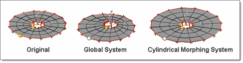 Figure 1. |
| stretch mesh around clusters | Ensure that the
surrounding mesh transitions smoothly when clusters are morphed.
Note: Due to the rigid body movement of
clusters, morphing performed on a mesh connected to one end
of a cluster will move that cluster and affect unmorphed
meshes connected to the cluster. If mesh stretching is
active, morphing will be applied to the unmorphed meshes as
well.
|
FEA Results Subpanel
The FEA Results subpanel determines how often FEA results display, and how they behave. By default only a single switch displays, but selecting any option from it besides off causes additional inputs to appear.
| Option | Action |
|---|---|
| analysis code | Select the analysis
code to be used.
|
| fea results frequency | Choose the frequency
of the results display.
Note: In order to use interactive FEA
results you must set up your model with all the necessary
cards to do an analysis for one of the following types:
Linear Static, Nonlinear Explicit, Stamping 1-step, or
Stamping incremental. HyperMorph
will not alter your model in any way in order to solve it.
HyperMorph will simply write
out a data file with the prefix "morphfea" and invoke the
specified solver. Errors during the solution process can be
found in output files located in the current working
directory.
|
| magnitude / components | Used when displaying
the results. Select whether to display the total magnitude or the X, Y, Z components of the results. |
| contour plot / assign plot | Choose between contour plot and assign plot when displaying the FEA results. |
| data type = | Click
solve to generate a results file and
then click simulation and data
type to select the desired options. Click prev and next to look through the available simulations and data types. Note: Can only be
selected after a solution has been performed on your
model.
|
| find maximum / maximum = | Used when displaying
the results. Select whether to let the software determine the maximum result, or specify the maximum result that is relevant to your task. |
| find minimum / minimum = | Used when displaying
the results. Select whether to let the software determine the minimum result, or specify the minimum result that is relevant to your task. |
| info title | Used when displaying
the results. Display an informational title in the modeling window. |
| mesh color | Used when displaying
the results. Select the color that the results mesh is drawn. |
| min/max titles | Used when displaying
the results. Display text/number titles for the minimum and maximum results in the modeling window. |
| simulation = | Click
solve to generate a results file, and
then click simulation and data
type to select the desired options. Click prev and next to look through the available simulations and data types. Note: Can only be
selected after a solution has been performed on your
model.
|
Parameters Subpanel
| Option | Action |
|---|---|
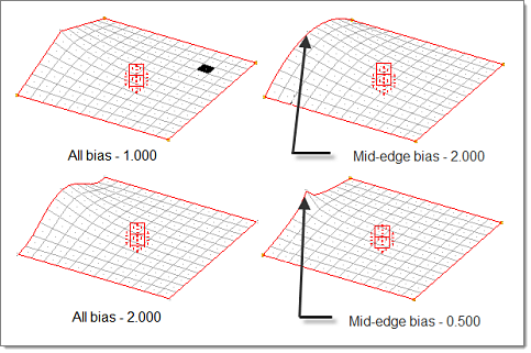
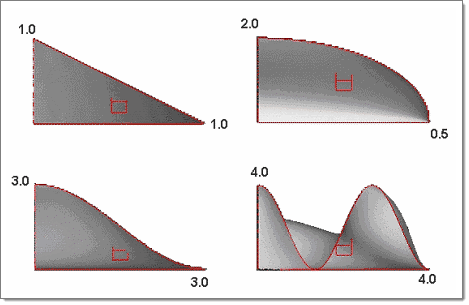
| biasing style | Choose a biasing
style.
|
| show domain icons / hide domains icons | Choose whether or not
to display the domain icons. Note: Edge domains will
always be displayed unless individually
masked.
|
| edge domain (color) | Select a new color to be assigned to all edge domains. |
| 2D domains (color) | Select a new color to be assigned to all 2D domains. |
| 3D domains (color) | Select a new color to be assigned to all 3D domains. |
| other domains (color) | Select a new color to be assigned to all 1D, global, and general domains. |
| faces (color) | Select a color for this type of entity to be drawn. |
| handle size | Specify a radius for the largest global handles (red) and the diameter of the largest local handles (yellow-orange). Dependent handle sizes are calculated relative to the independent handles. |
| handle tolerance | Specify the tolerance used for handle detection operations. Cannot exceed 5% of the handle size. |
| morphvolumes (color) | Select a color for this type of entity to be drawn. |
| symmetry (color) | Select a color for this type of entity to be drawn. |
| symmetry size | Specify how large symmetry indicators are drawn. |
Command Buttons
| Button | Action |
|---|---|
| plot | Display the results
for the solution most recently solved. HyperMorph will use the parameters
specified in this panel when plotting the results. Note: You can switch simulations and data types and
plot the results without needing to solve after switching.
The results will reflect the state of the model when a
solution was last performed which might differ from the current
state of the model (for example if an undo or redo was performed
on the model the results will be out of date). HyperMorph does not store any results for
previous model states and will overwrite the results file after
each solution. If you wish to save the results after any
solution make a copy of the results file
(morphfea.res for Linear Static and
Stamping 1-step solutions) and rename it. This file can be found
in the working directory. |
| redo | Redo the last morphing action. |
| redo all | Redo all recent morphing actions. |
| refresh | Refresh the model data file if any changes were made beyond just moving some of the nodes. To save time HyperMorph will only output new node locations when a new solution is requested instead of writing out the entire data file. In most cases HyperMorph will detect any changes made to the model and automatically refresh the model data file but if for some reason you make a change which does not appear to affect the results you may need to click refresh to force HyperMorph to update the model data file. |
| solve | Solve the model using the selected solver. HyperMorph will automatically plot the results for the selected simulation and data type or use the first results on the list if the fields are blank. Results files and solver output can be found in the current working directory. |
| undo | Undo the last morphing action. |
| undo all | Undo all recent morphing actions. |