Spot Panel
Use the Spot panel to create connectors that represent point connectors such as spot welds. These connectors can be realized as standard or custom weld representations.
Location: Connectors module
When the Spot panel is active, only spot-type connectors display in the modeling window; graphics for other connector types are suppressed until you exit the panel.
Subpanel Organization
- Spot Subpanel
- Create and realize spot connectors.
- Create Subpanel
- Create, but do not realize spot connectors.
- Realize Subpanel
- Realize an existing spot connector (no creation or editing is possible).
- Edit Subpanel
- Edit an existing spot connector.
- The first column contains everything related to connector creation and link detection.
- The second column contains everything related to realization type, post script and property assignment.
- The third column contains everything related to the final connection to the link entities.
Connector Creation and Link Detection Options
| Option | Action | ||
|---|---|---|---|
| location | Select the location of
the connector to be created.
|
||
| add location node as link | Store the selected
location node as an additional link of the link type node.
This checkbox appears when the location is defined by nodes. Many realization types do not work together with nodes as links. When these realization types are chosen the option is not provided. Note: Connectors can be created with different
types of entities; for example, a connector can be defined by selecting a
component on one side and an assembly on the other side. This can be done by
creating a connector to specify one of the entity types and selecting that
entity. Add the second entity by updating the connector via the add links
functionality in the Connector browser or the Add Links panel.
|
||
| spacing / density |
|
||
| preserve nodes | Preserve the position
of the nodes when you create and realize a connector. Note: Only
available if location is set to
nodelist/nodepath.
|
||
| split to points |
Split the line into individual points and create spot
connectors for each resultant point.
Note: Only available if location is set to
nodelist/nodepath or by a line.
|
||
| connectors | Select the connector(s) to be realized. | ||
| connect what | Select the entities to
become link candidates. Link candidates are certain entities of a chosen link
type, which are supposed to be connected during the realization. Entities
outside the tolerance are not taken into account.
|
||
| link state | Connect to either the
geometry or the elements of selected link entities. Note: Only
available when connect what is set to comps, assems, or
surfs.
|
||
| num layers |
Define how many thicknesses (layers) have to be connected at the connector position. When link detection is performed the valid connector links are established with respect to the given tolerance and the selected link candidates. By default the links are reduced to the minimum needed. The number of layers for spots is typically identical to the number of links, though the number of links can be lower in case of flaps. For spot connectors it is possible to set the number of layers to auto in order to identify and write the exact number of layers during link detection to each individual connector. |
||
| tolerance |
Define a distance from the connector location (per each test point). Only entities within this tolerance can be taken into account for the link detection and the final realization. Thus, the tolerance is used twice: first for the link determination and again for the realization. In the second step the tolerance is used to verify whether adequate link candidates are available to be connected. During pure connector creation on the Create subpanel, the tolerance is used for the link determination, but not necessarily stored on the connector unless the checkbox in front of the tolerance field is marked. In this way different tolerances can be used. The tolerance used during the realization process is always written to the connector. |
||
| connect when |
Select when to perform link detection.
|
||
| re-connect rule |
While realizing the connector, Engineering Solutions
looks for link entities based on the re-connect rule.
Tip: This option is
useful in situations where the parts to be connected have been
changed/replaced.
|
||
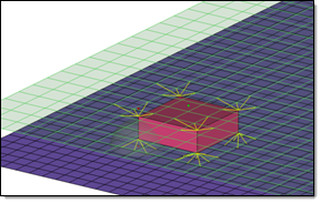
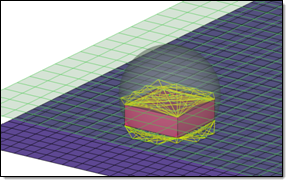
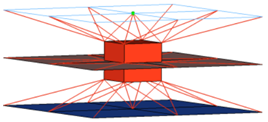
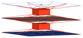
| use rbe3 radius | RBE3 elements are
typically created with three or four legs dependent on the
element type (quadface, triaface) the projection of the
appropriate hexa node is landing on. To be more accurate,
especially regarding different mesh sizes, an rbe3 radius can be
defined, so that more nodes nodes can be joined by each RBE3
element. In any case, at least one element face will be joined
by each RBE3 element. Figure 1. use rbe3 radius Disabled  Figure 2. use rbe3 radius Enabled All of the nodes of the appropriate link (outer nodes, if it is a solid link), which are positioned inside a sphere around the projection point, are considered to be joined to the RBE3 element. A feature angle is also considered. The nodes that are on a different side of the feature edge than the projection point will not be joined to the RBE3 element. When enabled you must define:
Note: Only available for the realization type acm
(general).
|
Post Script and Property Assignment Options
| Option | Action |
|---|---|
| type |
Select the realization type which should be used. The
realization type is a description of the FE representation.
Note: The available
realization types are dependant on the configuration file loaded under fe file
on the general connector Options panel.
|
| post script treatment |
Choose whether or not a post script has to be used for
the specific realization type. These scripts are used to automatically create
materials, properties, and/or contacts necessary for realizing the connectors.
|
| elems to current comp / elems to connector comp |
Select which component the FE representations
are stored in once they have been realized.
Note: Only available in the realize subpanel when post script treatment is set
to no/skip post script.
|
| property treatment |
Select a property treatment.
Note: Only available when post script treatment is set to no/skip post
script.
|
| direct property assignment |
Directly assign the property, otherwise assign the
property to the destination components.
Note: Only available when property treatment
is set to property =, and the solver interface is Nastran, OptiStruct, Radioss or Abaqus.
|
Specific Realizations Options
| Option | Action | ||
|---|---|---|---|
| diameter / use diameter mapping | This field is used for
realizations based on hexa elements such as ACM, where the size
of the realized element (hexa, and so on) is created based on
the diameter value, or for certain realization types where the
diameter is used by a post script. The size of the hexa face is calculated from the diameter value . When you have weld
nuggets from hexa patterns (more than one hexa), the
diameter will be measured from two opposite
nodes.
|


| Option | Action |
|---|---|
| thickness | Select a thickness
option used for dimensioning and positioning hexas.
|
| num hexas | Create a hexa cluster
with 1, 4, 8, 12, 16 or 32 hexas, which are arranged in a
predefined pattern.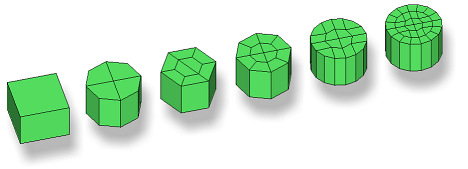 Figure 9. Note: Available for all ACM realization
types.
|
| coats | Define the number of hexa elements required along the thickness. Multiple solid coats are supported. |
| orthogonal faces | Force the creation of
perfectly orthogonally-shaped hexas. Figure 10. . The two leftmost realizations were performed with the orthogonal faces option enabled. Note: Available for any kind of ACM weld, if num hexas is
set to 1.
|
| Option | Action |
|---|---|
| create vector | Create orthogonal vectors for each CBUSH element created during the sealing realization. These vectors are used to define the orientations of the CBUSH elements, which is important to the stiffness defined in the related PBUSH cards. |
| Option | Action | ||||||
|---|---|---|---|---|---|---|---|
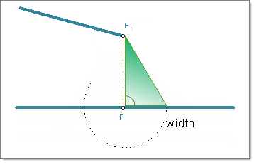
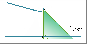
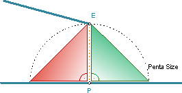
| width | Specifies the length
of a penta. Note: Available for: penta (mig + L), penta (mig +
T), and penta (B).
|
||||||
| depth | Specifies the depth of
a penta. Note: Available for: penta (mig + L), penta (mig + T),
and penta (B).
|
||||||
| fitted/equilateral/ equilateral-fitted |
Select the size and shape
of a penta.
Note: Available for: penta (mig + L).
|
||||||
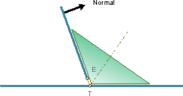
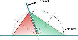
| right-angled |
Create a right-angled penta that is oriented around the
bisector. Clear this checkbox to create an angle adapted penta.
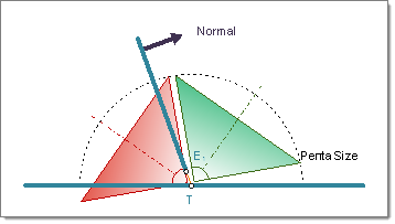 Figure 14. Right-Angled T-weld Penta Created on Both Sides of the Normal 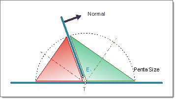 Figure 15. Angle Adapted T-weld Penta Created on Both Sides of the Normal Note: Available for: penta (mig + T).
|
||||||
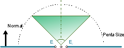
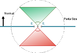
| both sides/positive sides/negative sides |
Select which side of the normal to create
the penta on.
Note: Available for: penta (mig + L), penta (mig + T), and penta
(B).
|
| Option | Action |
|---|---|
| use shortest projection for center / use connector position for center / use coarse mesh for center |
|
| max nodes per layer | Specify the maximum number of nodes per layer to attach to the RBE3 element. The minimum number of nodes you can specify is 3. |
| Option | Action | ||||
|---|---|---|---|---|---|
| use shortest projection for center / use connector position for center |
Note: (Only available for type CWELD (general), when the
nodetype GS (point to face) is selected)
|
||||
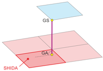
| CWELD Type | Select a CWELD type
definition.
Note: Only available for type CWELD
(general).
|
||||
| Nodetype | Select a nodetype.
Available nodetypes depend upon the CWELD type selected.
Note: Only available for type CWELD
(general).
|
||||
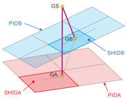
| recenter GS | Reposition the initial
GS position between node GA and GB. After re-positioning,
projections are done a second time to identify the correct
node/element IDs.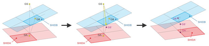 Figure 19. Note: Only available for type CWELD (general), when the
nodetype GS (point to face) is selected.
|
||||
| centered quad | Perform a mesh
modification during the realization to guarantee that the CWELD
nodes will be close to the CQUAD centroids. Specify a desired
quad size in the quad size field, or click
centered quad to access
additional centered quad settings.
Note: Only available for type CWELD (general), CWELD
(GA-GB ELEMID) and CWELD (GA-GB
GRIDID).
|


Final Connection to Link Entities Options
| Option | Action |
|---|---|
| mesh dependent / mesh Independent |
Determine whether the realizations require
a node connection.
|
| adjust realization / adjust mesh |
Note: Only available when mesh independent is selected.
|
| quad transition / remesh / smooth | Select a mesh
adjustment options.
Note: Only available when mesh dependent and adjust mesh
are selected.
|
| imprint / skip imprint |
Note: Only available when mesh independent, adjust mesh, and quad transition are
selected.
|
| resolve conflicting imprints | Resolve small
conflicts between overlapping transition meshes automatically.
Larger conflicts may require a manual imprint. Note: Only
available when mesh independent, adjust mesh, quad
transition, and imprint are selected.
|
| allow snapping |
Note: Only available when mesh independent, adjust mesh, and
quad transition are selected.
|
| quad size | Specify a preferred
size for the transition quads. Clear this checkbox to use the
default element size from the Connector Options panel.
Note: Only available when mesh independent, adjust mesh, and
quad transition are selected.
|
| find nearest nodes / project and find nodes / ensure projection | Select how the
realization will adjust to locate nodes in the linked entities
in order to establish links. Note: Only available when adjust
realization is selected.
|
Edit Subpanel
| Option | Action |
|---|---|
| connectors | Select the connectors
to edit. Click edit to update the selected connectors with respect to the new chosen settings. The connectors will become unrealized. |
| spacing = / density = |
|
| end offset = / half spacing |
|
| split to points |
Split the line into individual points and create spot
connectors for each resultant point.
Note: Only available if location is set to
nodelist/nodepath or by a line.
|