Morph Volume Panel
Use the Morph Volume panel to create, edit, save, load, convert, and delete morph volumes.
Location: Tools page > HyperMorph module
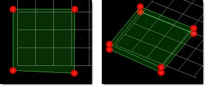
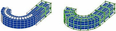
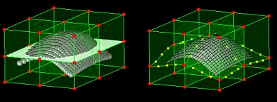
A morph volume (or "mvol") is a six-sided prism that can be used to manipulate a mesh by manipulating the shape of the morph volume. Morph volumes are very malleable; the length and curvature of each edge can be modified independently of the others, and adjacent morph volumes can be linked through various tangency conditions. This malleability allows you to enclose a given mesh with morph volumes, alter the morph volumes to fit your model, and then change the shape of your model by modifying the morph volumes. Morph volumes present a simple, powerful, and intuitive way to morph.
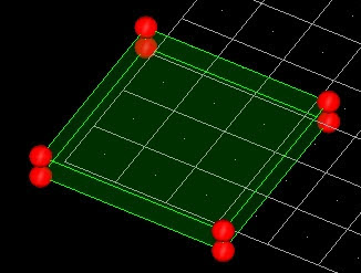
Figure 1. Morph Volume with Handles at the Corners
Create Subpanel
| Option | Action | ||
|---|---|---|---|
| creation method |
|
||
| auto-tangent |
If tangency is selected, a continuous tangency
condition will be applied across adjacent edges for the new morph volumes. Tangency
ensures smooth morphing between morph volumes.
Note: Tangency conditions
can extend across multiple morph volumes, meaning that handle movements at one
end of the morph volume matrix can potentially affect every morph
volume.
|
||
| buffer % | Specify the amount of empty space between the selected nodes or elements and the faces of the created morph volumes, based on the average size of the morph volume to be created. For instance, if a mesh measured 30x30x30 and a 10% buffer percentage was selected, the morph volume would be created measuring 36x36x36, which would give it a 10% (3 unit) buffer zone between each side and the enclosed mesh. | ||
| drag direction |
Note: Available when any of the "drag" creation methods are
selected.
|
||
| elems (drag elements) | Select the elements you wish to drag. | ||
| enclose elems / enclose nodes | Choose the entities that you wish the morph volume to enclose. | ||
| fit method | Choose what the morph volume can do after
creation to better fit the elements that it encloses.
|
||
| global system / local system |
|
||
| handle placement |
Choose where the morph volume's handles are located.
Note: If you choose corners and edges, you must also specify the number of
handles to create on each edge. You can specify 1 to 5 edge handles, which will
be evenly spaced along the edge between the corner handles.
|
||
| morphvolumes | Select the existing
morph volumes that you wish to reflect in order to create new
volumes. Note: Only available when the creation method is set
to reflect mvols.
|
||
| node list | Select the nodes that
you wish to enclose or drag. Note: Only available when the
creation method is set to pick and enclose or drag
nodes.
|
||
| on drag | Specify the number of
morph volumes that will be created along the drag direction.
Thus, if you had selected six morph volumes and set on drag to
5, a total of 30 (6 x 5) new morph volumes will be
created. Note: Only available when the creation method is set
to any of the "drag" options.
|
||
| on face x | On face x and on face
y are the number of morph volumes which will be created for a
rectangular matrix in the local x and y directions. The local x
direction is determined as being either the global x axis as
projected on to the plane normal to the drag direction, or if
the drag direction is perpendicular to the global x axis then
the projection of the global y axis is used. The local y
direction is perpendicular to the local x direction and the drag
direction. Note: Only available when the creation method is
set to drag matrix (rect), drag lines (rect), or drag nodes
(rect).
|
||
| on face y | On face x and on face
y are the number of morph volumes which will be created for a
rectangular matrix in the local x and y directions. The local x
direction is determined as being either the global x axis as
projected on to the plane normal to the drag direction, or if
the drag direction is perpendicular to the global x axis then
the projection of the global y axis is used. The local y
direction is perpendicular to the local x direction and the drag
direction. Note: Only available when the creation method is
set to drag matrix (rect), drag lines (rect), or drag nodes
(rect).
|
||
| register all inner nodes |
Associate all nodes enclosed by the morph volume with that volume. When registering nodes to multiple morph volumes or all morph volumes, nodes will only be registered to the morph volume that they are inside. This provides a convenient way to register masses of nodes rapidly. Nodes that are selected to be registered but that do not lie within a morph volume will still be registered to all morph volumes but will not be affected by any morph volume morphing. However, when switching from inactive to active status for morph volumes, all registered nodes are re-registered to the morph volumes, which allows for nodes to become registered to a new morph volume, or all morph volumes, depending on their location. The process of registering nodes allows you to control which nodes are morphed by morph volumes and which are not (such as when you are matching one mesh to another), and allows you to make one morph volume dependent on another by registering its handle nodes to a morph volume that encloses it. After morphing morph volumes while they are inactive, unregistered nodes may end up inside the morph volumes. These will not be automatically registered when the morph volume status is switched to active. You will need to register these new nodes manually. Note: Only available when the creation method is set to pick and
enclose or reflect mvols.
|
||
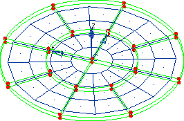
| r density | Specify the r density,
which is the number of morph volumes which will be created in
the radial direction. Note: Only available when the creation
method is set to drag matrix (cyl), drag lines (cyl), or
drag nodes (cyl).
|
||
| symmetries | Select the reflective
symmetry around which you wish to reflect the specified
morphvolumes. Note: Only available when the creation method
is set to reflect mvols.
|
||
| t density | Specify the t density,
which is the number of morph volumes that will be created in the
outer layer about the drag axis. Note: Only available when the
creation method is set to drag matrix (cyl), drag lines
(cyl), or drag nodes (cyl).
|
||
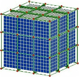
| X density / Y density / Z density | Specify the number of
morph volumes that will be created along each axis. For example: when creating a single-layer, 3 x 3 matrix of volumes around a 2D mesh, you might specify 3 for the X and Y densities and 1 for the Z density. For a cylindrical matrix, the x density refers to the number of morph volume layers in the radial direction and the y density refers to the number of morph volumes in the outermost ring. Note: Only available when the creation method is
set to create matrix.
|
Update Mvols Subpanel
| Option | Action |
|---|---|
| auto-tangent |
If tangency is selected, a continuous tangency
condition will be applied across adjacent edges for the new morph volumes. Tangency
ensures smooth morphing between morph volumes.
Note: Tangency conditions
can extend across multiple morph volumes, meaning that handle movements at one
end of the morph volume matrix can potentially affect every morph
volume.
|
| buffer % | Specify the amount of empty space between the
selected nodes or elements and the faces of the created morph volumes, based on
the average size of the morph volume to be created. For instance, if a mesh
measured 30x30x30 and a 10% buffer percentage was selected, the morph volume
would be created measuring 36x36x36, which would give it a 10% (3 unit) buffer
zone between each side and the enclosed mesh. Note: The fit through nodes
option is only available for fit faces operations performed
by face.
|
| by face / by mvol | Select either by face
or by mvol, then select the morph volume faces or morph volumes
to be fitted. Note: When you select by mvols, all
external faces of the morph volume will be
fitted.
|
| fit method | Choose the type of
fitting applied to the faces.
|
| free inner faces | Move the inner faces (faces shared by more than one selected morph volume) freely during the shrinking operation. |
| handle placement: |
Choose where the morph volume's handles are located.
Note: If you choose corners and edges, you must also specify the number of
handles to create on each edge. You can specify 1 to 5 edge handles, which will
be evenly spaced along the edge between the corner handles.
When performing a fit faces operation, choose to keep the current handles (use current) or specify a number of handles per edge after the volume faces are fitted (handles/edge). |
| implicit mode / explicit mode | Choose the algorithm
used when shrinking the selected morph volumes.
|
| max. iter | Specify the maximum number of iterations to perform when shrinking morph volumes. |
| morphvolumes | Select the existing morph volumes that you wish to update. |
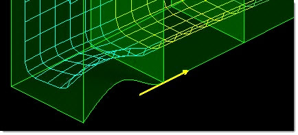
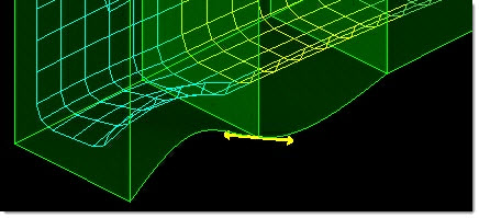
| project normal / project by vector | Choose whether to project the faces normal to their current orientation or along a vector. If using a vector, point the vector in the direction the target nodes or elements will end up relative to the faces, after the faces have been fitted. |
| register all inner nodes |
Associate all nodes enclosed by the morph volume with that volume. When registering nodes to multiple morph volumes or all morph volumes, nodes will only be registered to the morph volume that they are inside. This provides a convenient way to register masses of nodes rapidly. Nodes that are selected to be registered but that do not lie within a morph volume will still be registered to all morph volumes but will not be affected by any morph volume morphing. However, when switching from inactive to active status for morph volumes, all registered nodes are re-registered to the morph volumes, which allows for nodes to become registered to a new morph volume, or all morph volumes, depending on their location. The process of registering nodes allows you to control which nodes are morphed by morph volumes and which are not (such as when you are matching one mesh to another), and allows you to make one morph volume dependent on another by registering its handle nodes to a morph volume that encloses it. After morphing morph volumes while they are inactive, unregistered nodes may end up inside the morph volumes. These will not be automatically registered when the morph volume status is switched to active. You will need to register these new nodes manually. |
| registered nodes / fit to nodes / fit to elems | Select what to fit the
selected morph volumes to. If you are fitting to selected elements or nodes you are also given entity collectors to select them, as well as the option to register those nodes to the morph volumes being fit. When performing a register nodes operation, only the registered nodes entity collector displays. |
| single morph volume / multiple morph volumes / all morph volumes | When performing a register nodes operation, choose which morph volumes you wish to register nodes to. The "single" and "multiple" options present entity collectors, while the "all" option requires no further input. |
| smoothness | Higher values will give a flatter result and lower numbers will allow more curvature. The smoothness does not apply when using slide faces or tilt faces. |
| tolerance | When joining mvols with the equivalence option, specify a tolerance to determine which volumes will join. If the faces of two morph volumes are within the tolerance distance from each other and have been selected, they will be joined. (Unselected volumes will not be joined regardless of tolerance.) |
| update operation | Choose the type of
update you wish to perform.
|
Update Edges Subpanel
| Option | Action |
|---|---|
| by edges / by nodes / by mvols | Choose how to ends
will be selected.
Note: Only available when updating ends.
|
| connect all edges / connect edges between / connect along vector / connect radial edges / connect circum. edges |
Note: Only available when updating ends, by mvols, with
continuous tangency.
|
| create handles | Create handles on the edge after it is updated. |
| end node | Select an edge by
selecting one of its end points. An edge runs from one corner of
a morph volume to the other regardless of any tangency
conditions. Note: Only available when updating ends by
edges.
|
| fix along | Edges which run
roughly parallel to the specified vector will gain a fixed
tangency. Note: Only available when using update ends, by
mvols, with fixed tangency.
|
| free / fixed / main-secondary / continuous | Select a types of
tangency to apply.
Note: Only available when using update ends and by
mvols.
|
| free all edges / free edges between / free along vector / free radial edges / free circum. edges | Choose a method for
selecting the edges to free.
Note: Only available when using update ends and by
mvols.
|
| main, secondary | Select the main
morph volumes and secondary morph volumes. Note: Only available when
using update ends, by mvols, and with main-secondary
tangency.
|
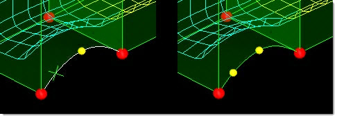
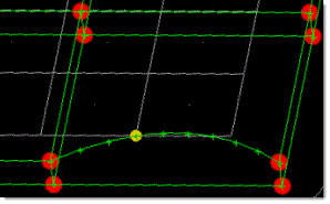
| mid-nodes on edge / add mid-node |
 Figure 21. Note: Available when updating nodes.
|
| node a, node b | Specify the ends of
the desired edge. Note: Available when updating nodes by pick end
nodes, or when updating ends by nodes.
|
| pick edge / pick end nodes / node list | Choose how to select
the edge that you wish to update nodes for. Note: Available when
updating nodes.
|
| tangencies | Select a color to
display the tangency markers (arrows). Note: Available when
updating ends.
|
| update nodes / update ends / delete mid-nodes | Select the type of edge update you wish to make. |

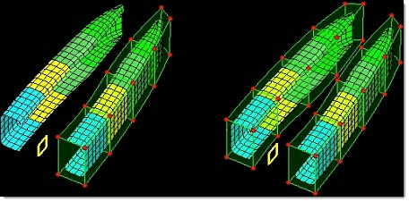
Split/Combine Subpanel
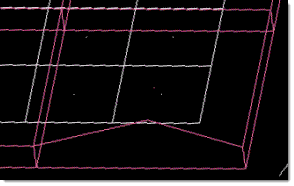
Use the Split/Combine subpanel to combine multiple morph volumes into a single larger one, or to split a morph volume into multiple smaller ones.
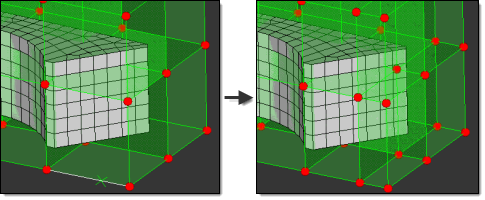
Figure 22.
| Option | Action |
|---|---|
| by edges / by nodes | When splitting morph
volumes, choose how you specify the location of the split.
|
| combine mvols / split mvols | Choose the type of operation to perform. |
| create handles | When splitting a morph
volume, create handles on the new morph volumes. Clear this checkbox to create nodes, but not handles on the new volumes' edges. |
| keep tangent | Set the edges of the
new (combined) morph volume to continuous tangency with the
edges of morph volumes adjacent to it. If you clear this checkbox, the new (combined) morph volume's edge curvature will not affect or be affected by the edge curvature of the volumes adjacent to it. Note: Available when combine
mvols is selected.
|
| make tangent | Make the edges of the
newly-created morph volumes tangent with the volumes adjacent to
them. Note: Available when split mvols is
selected.
|
| morph volume | Select the volumes
that you wish to combine. Note: Available when combine mvols is
selected.
|
| single split / # of splits |
|
Save/Load Subpanel
| Option | Action |
|---|---|
| file: | Specify the file path and name of the morph volume file, either the file to save mvols to, or the one to load them from. You can enter the filename and path, or click browse to navigate to and select it. |
| morph volumes | Select the mvols that you wish to save to the specified file. |
| register all inner nodes | Automatically assign mesh nodes to the loaded morph volumes. |
| save mvols / load mvols | Choose whether the specified file will be saved or loaded. |
| save shapes | Save shapes (morphs) to the same file as morph volumes. |
Convert Subpanel
 |
 |
| Option | Action |
|---|---|
| auto-tangent |
If tangency is selected, a continuous tangency
condition will be applied across adjacent edges for the new morph volumes. Tangency
ensures smooth morphing between morph volumes.
Note: Tangency conditions
can extend across multiple morph volumes, meaning that handle movements at one
end of the morph volume matrix can potentially affect every morph
volume.
Note: Only available when converting hexas to mvols.
|
| elems | Select the elements
that you wish to convert in your model, or use the extended
entity selection menu. Note: Only available when converting hexas
to mvols.
|
| handle placement |
Choose where the morph volume's handles are located.
Note: If you choose corners and edges, you must also specify the number of
handles to create on each edge. You can specify 1 to 5 edge handles, which will
be evenly spaced along the edge between the corner handles.
Note: Only available when converting hexas to mvols.
|
| hexas to morphvolumes / morphvolumes to hexas | Choose which action will be performed. |
| morph volumes | Select the mvols that
you wish to convert. Note: Only available when converting mvols
to hexas.
|
| register all inner nodes | Automatically assign
each of the nodes located within a new morph volume to that
volume. Note: Only available when converting hexas to
mvols.
|
Parameters Subpanel
| Option | Action |
|---|---|
| face drawing | Choose how the flat
faces of morph volumes are drawn.
|
| global influences | Choose how morph
volumes respond to global influences.
|
| handle size | Specify the radius of corner node handles, the largest type of handle used by morph volumes. Other handles are drawn slightly smaller and in a different color. The units used for this setting are the same as those used by your model. |
| Interpolation mode | Choose how edge curves
are calculated.
|
| morph volume solver | Choose which solver is
used for determining the morphing of the nodes inside the morph
volumes.
|
| morphvolumes (color) | Select a color to assign to morph volumes. |
| mvols: active, inactive, or skin only | Turn the morph
volumes' ability to affect the mesh on and off, and/or delay
morphing of the interior of solid meshes.
Note: Switching the selector away from
mvols:skin only will automatically trigger the morphing of
the nodes inside the solid mesh.
|
| pts for edge draw | Specify how many points each morph volume edge uses to represent curves. Use larger numbers for smoother curves, or smaller numbers for faster rendering. The default number is ten. |
| register all inner connectors, register displayed inner connectors, don't register connectors | Specify the behavior
for automatically registering enclosed connectors when creating
new morph volumes.
|
| register tolerance | Specify how far
outside the boundaries, relative to the size of the morph
volume, a node may be from a given morph volume to be registered
to it. Thus, larger values allow nodes further outside a volume
to still map to it. Note: Nodes near the boundary
between two morph volumes maybe mapped to either one.
|
Command Buttons
| Button | Action |
|---|---|
| combine | Combine selected mvols into one. |
| convert | Convert mvols to hexas or vice-versa |
| create | Create a new mvol. |
| delete | Delete the selected entities. |
| fit | Fit mvols to their registered mesh nodes as described in the update subpanel. |
| join | Join selected mvols
together. Note: The volumes are not combined into a
single volume; they simply share an edge (This differs from
combine).
|
| load | Load the specified file. |
| reject | Reject the creation or update (tangency, split/combine, and so on) of a morph volume. |
| review | Fill the node selector with the currently registered nodes. Use the left and right mouse buttons to select and unselect nodes to be registered. |
| save | Save the specified file. |
| shrink | Shrink the mvols in accordance with your specifications. |
| split | Split the specified mvol into two. |
| update | Update the selected mvol nodes or handle placement. |