Scale Panel
Use the Scale panel to increase or decrease an entity's dimensions.
Location: Tool page
Scaling can be proportional or non-proportional.
When working with cylindrical or spherical coordinate systems, the x scale represents the radial direction. Scaling options for angle axes are removed, meaning that in cylindrical systems the y scale = option disappears, and in spherical systems both y scale = and z scale = disappear.
To undo scaling, select the opposite function without changing the scaling factors or origin. Each click of scale + reverses a click of scale - and vice versa.
When scaling components, all of the geometry (lines, surfaces, points) and elements (nodes) contained in the selected components are automatically scaled.
If you don't select a node for the scaling origin, the global or local coordinate system's origin is used.
Since scale factors act as multipliers or divisors, they cannot be zero, and a factor of one produces no change in the corresponding direction. Decimal factors are acceptable and can be helpful when converting a model to different units of measurement.
Non-uniform scaling can distort meshes and models. Uniform scaling can distort meshes if only some of an entity's nodes are scaled.
Panel Options
| Option | Action |
|---|---|
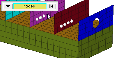
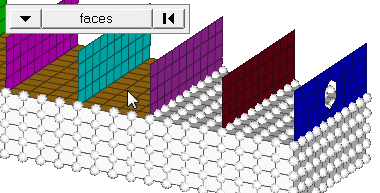
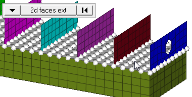
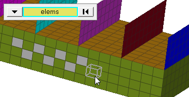
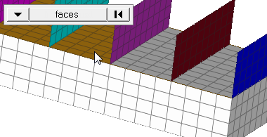
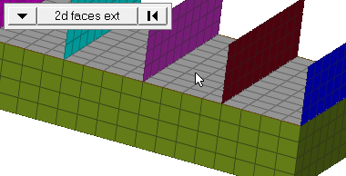
| entity selector | Select entities for
scaling. When you select nodes or elems, click the switch
to change the selection mode.
|
| origin | Entities scale based on their position relative to an origin node. Double-click node and enter a node ID, or click once and then select a node in the modeling window to set the origin node. |
| coordinate system | Choose a type of
coordinate system.
|
| x scale = | Specify a factor by which the selection will scale in the selected system's x direction. |
| y scale = | Specify a factor by which the selection will scale in the selected system's y direction. |
| z scale = | Specify a factor by which the selection will scale in the selected system's z direction. |
| face angle / individual selection |
|
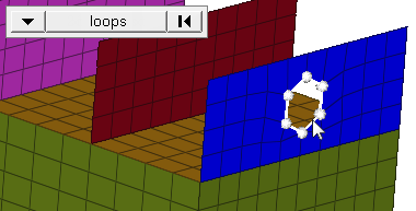
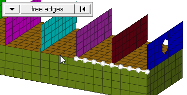
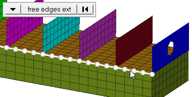
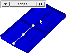
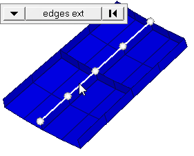
| edge angle |
Split edges that belong to a given face. When the edge
angle is 180 degrees, edges are the continuous boundaries of faces. For smaller
values, these same boundary edges are split wherever the angle between segments
exceeds the specified value. A segment is the edge of a single element.
Important: Only available when the entity selector is set to nodes and the
selection mode is set to free edges, free edges ext, edges, or edges
ext.
|
Command Buttons
| Button | Action |
|---|---|
| uniform | Click to specify the desired scaling factor. The x scale, y scale, and z scale fields automatically change to this value so that the scaling is proportional. |
| scale+ | Increase the selection's dimensions relative to the coordinate system and origin chosen. The scaling factor acts as a multiplier. For example, a factor of 2 doubles the selection's dimensions. |
| scale- | Decrease the selection's dimensions relative to the coordinate system and origin chosen. The scaling factor acts as a divisor. For example, a factor of 2 halves the selection's dimensions. |
| return | Accept the current scaling and exit the panel. |