Contactsurfs Panel
Use the Contactsurfs panel to create and modify contactsurf entities.
Location: Analysis page > Safety module
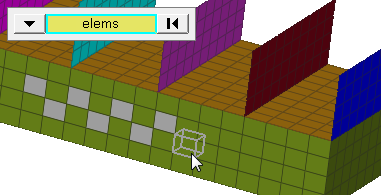
The contactsurf entity, used in most crash solvers, is defined using elements (1D, 2D, 3D) and their respective face codes. A contactsurf is displayed as an arrow on the selected element faces. The direction of the arrow is along the element normal that defines contactsurfs.
A contactsurf has the following parameters:
- Name
- Color
- Card image
- Elements
Elems Subpanel
| Option | Action |
|---|---|
| name | Enter a name for the entity. |
| card image | Select a valid card image. Options depend on the current solver interface. |
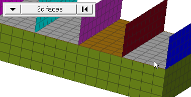
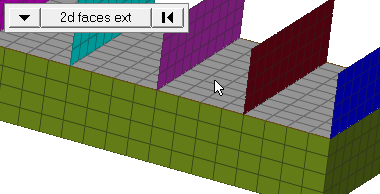
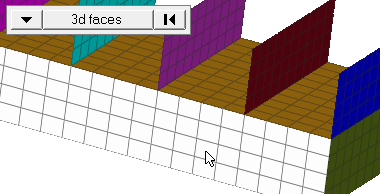
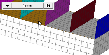
| elems selector | Select the elements to
include in the contactsurf entity. Use the switch to change
the selection mode.
Note: Changing the selection mode will
clear your current selection. Use the Entity Editor to
select elements using multiple selection
modes.
|
| reverse normals | Set the direction of the contactsurf to be opposite of the elements normal. |
| color | Select a color for the entity. |
| face angle / individual selection |
|
Solid Faces Subpanel
| Option | Action |
|---|---|
| name | Enter a name for the entity. |
| card image | Select a valid card image. Options depend on the current solver interface. |
| elems selector | Select the elements to
include in the contactsurf entity. Use the switch to change
the selection mode.
Note: Changing the selection mode will
clear your current selection. Use the Entity Editor to
select elements using multiple selection
modes.
|
| nodes on face / nodes on edge | Nodes on edge is valid for 1D and 2D elements only. |
| nodes | Select nodes that denote a face or an edge to define contactsurf. |
| reverse normals | Set the direction of the contactsurf to be opposite of the elements normal. |
| color | Select a color for the entity. |
| face angle / individual selection |
|
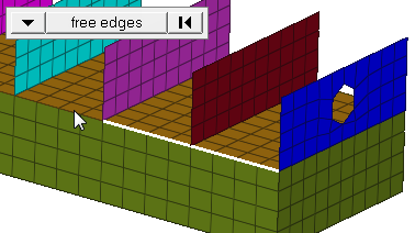
| Edge angle |
Split edges that belong to a given face. When the edge
angle is 180 degrees, edges are the continuous boundaries of faces. For smaller
values, these same boundary edges are split wherever the angle between segments
exceeds the specified value. A segment is the edge of a single element.
Note: Only
available when the selection mode is set to free edges.
|
Remove Elems Subpanel
| Option | Action |
|---|---|
| contactsurf selector | Select the contactsurf that has the elements that need to be removed. |
| elems selector | Select the elements
that should be removed from the contactsurf entity. Use the
switch to change the selection mode.
Note: Changing the selection mode will clear your
current selection. Use the Entity Editor to select
elements using multiple selection
modes.
|
| face angle / individual selection |
|
| edge angle |
Split edges that belong to a given face. When the edge
angle is 180 degrees, edges are the continuous boundaries of faces. For smaller
values, these same boundary edges are split wherever the angle between segments
exceeds the specified value. A segment is the edge of a single element.
Note: Only
available when the selection mode is set to free edges.
|
Adjust Normals Subpanel
The normal of a contactsurf defines all the faces/edges that will eventually define
contact interface with an adjacent part. For pressures/forces/temperatures, it is
the direction in which they act.
| Option | Action |
|---|---|
| contactsurf selector | Select the contactsurf for which the normal is to be changed. |
| all elems / by elems |
Note: Changing the selection mode will clear
your current selection. Use the Entity Editor to select
elements using multiple selection modes.
|
| face angle / individual selection |
|
| edge angle |
Split edges that belong to a given face. When the edge
angle is 180 degrees, edges are the continuous boundaries of faces. For smaller
values, these same boundary edges are split wherever the angle between segments
exceeds the specified value. A segment is the edge of a single element.
Note: Only
available when the selection mode is set to free edges.
|