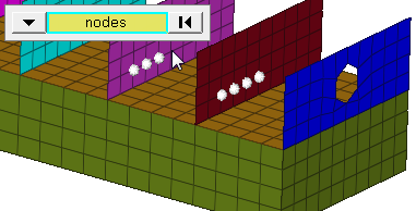
Select all of the nodes on 2D and 3D faces. If there are discontinuities
on a 2D face, then only the nodes inbetween the discontinuities will be
selected. Figure 5. Example: Faces Selection
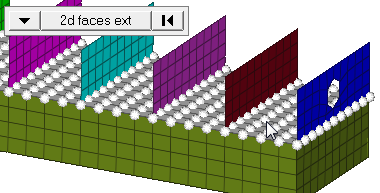
2D faces ext
Select all of the nodes on a 2D face that contain discontinuities. Figure 6. Example: 2D Faces Ext Selection
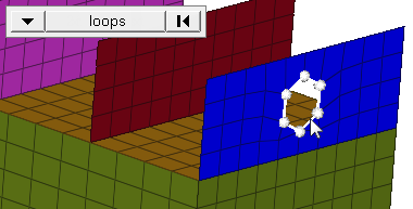
loops
Select all of the nodes on continuous free edges that make a closed loop
simultaneously, such as the perimeter of a hole.
Important: Only valid for SHELL elements.
Figure 7. Example: Loops Selection
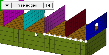
free edges
Select all of the nodes on free edges of elements. If there are
discontinuities on an edge, then only the nodes on the free edges
inbetween the discontinuities will be selected.
Important: Only valid for SHELL elements.
Figure 8. Example: Free Edges Selection
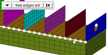
free edges ext
Select all of the nodes on free edges of elements that contain
discontinuities.
Important: Only valid for SHELL
elements.
Figure 9. Example: Free Edges Ext Selection
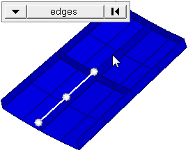
edges
Select all of the nodes on free edges or shared edges (butt joints,
L/corner joints, and T-joints) of elements. If there are discontinuities
on an edge, then only the nodes on the edge inbetween the
discontinuities will be selected.
Important: Only valid for
SHELL elements.
Figure 10. Example: Edges Selection
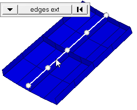
edges ext
Select all of the nodes on free edges or shared edges (butt joints,
L/corner joints, and T-joints) of elements that contain
discontinuities.
Important: Only valid for SHELL
elements.
Figure 11. Example: Edges Ext Selection
Elements
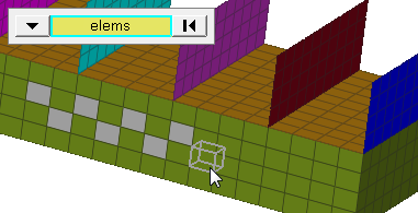
elems
Select individual elements, or select all of the elements contained by a
component or on a surface. Figure 12. Example: Elems Selection
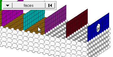
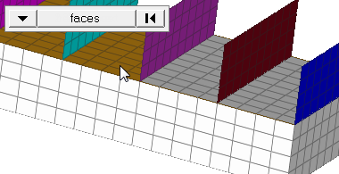
faces
Select all of the elements on 2D and 3D faces. If there are
discontinuities on a 2D face, then only the elements in between the
discontinuities will be selected. Figure 13. Example: Faces Selection
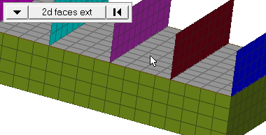
2D faces ext
Select all of the elements on a 2D face that contain
discontinuities. Figure 14. Example: 2D Faces Ext Selection
coordinate
system
Choose a coordinate
system type.
Global System
Translate entities relative to the global coordinate
system.
Local System
Translate entities relative to a local coordinate
system.
Use the base node selector to specify an origin for
the translation. While this translation origin is
unimportant within rectangular coordinate systems,
it may affect the translation when using cylindrical
and spherical coordinate systems. When no node is
selected as the base node, the selected local
system's origin serves as the base node.
Local systems can be rectangular, cylindrical, or
spherical, and are created in the Systems
panel.
direction
selector
Select the direction
in which selected entities will be moved.
magnitude =
Choose between a
specified number of units or a derived one.
magnitude =
Specify a non-zero number.
N2-N1
Select the vector between N1 and N2 nodes that
determines both the magnitude and the
direction.
scale=
Specify a value to
scale the vector between the N1 and N2 nodes. The value you
specify must be between 0.1 and 10. By default, the scale value
is 1.
Note: Available when magnitude= N2-N1.
face angle /
individual selection
face angle
Angle between the normal of facets that share an element edge. A facet
can either be a shell element itself, or one of the faces of a solid
element. The normal of triangular facets is that of the plane defined
three corner vertices. Whereas, the normal of quadrilateral facets is
calculated by taking the cross-product between its two diagonals. This
special treatment for quadrilaterals is because a warped shape does not
lie completely on a plane.
individual selection
Select individual elements on a face or select individual free/shared
edges of elements.
edge angle
Split edges that belong to a given face. When the edge
angle is 180 degrees, edges are the continuous boundaries of faces. For smaller
values, these same boundary edges are split wherever the angle between segments
exceeds the specified value. A segment is the edge of a single element.
Important: Only available when the entity selector is set to nodes and the
selection mode is set to free edges, free edges ext, edges, or edges
ext.
Command Buttons
Undo by translating in the opposite direction without changing any of the
input data (for example use the same direction and magnitude settings).
When translating components, all of the geometry (points, lines, surfaces,
and connectors) and elements (nodes) contained in the component are
automatically translated.
Translating nodes or elements does not change connectivity or continuity of
a mesh.
Translating only some of the nodes of an element may result in distortion of
the element.
Translating surfaces may affect edge topology, that is, shared edges
becoming free edges.
Translating elements or surfaces independently breaks any associations
between the surfaces and the elements (nodes) created on them. Using reject
will restore the associations if only one translation has been made, but
translating in the opposite direction (as described above for "undoing" a
translation) will not do so. Lost associations can also be restored via the
Node Edit panel.
Translating realized connectors will not unrealize them or translate the
associated elements.
When using spherical or cylindrical local coordinate systems, the x-axis,
y-axis, and z-axis buttons in the plane selector don't change. In such
cases, the x-axis, y-axis, and z-axis options correspond to the first,
second, and third axes of such systems.
Button
Action
translate +
Translate the selection in the positive
direction. For example, when translating nodes along the x-axis
this would move each selected node to a higher X coordinate
value.
Note: If the magnitude is negative this
actually moves the coordinates to lower X
values.
translate -
Translate the selection in a negative direction.
For example, a node at X,Y,Z coordinates (50,33,42) translated
along the global x-axis with a magnitude of 5 would move to
(45,33,42).
reject
Revert the last translation. Only the most recent
translation can be rejected; to undo multiple translations,
simply translate in the opposite direction. Each positive
translation can be undone by a negative translation of the same
magnitude and direction.
return
Complete the translation and exit the Translate
panel.