Solids Panel
Use the Solids panel to create solid geometry using a wide variety of methods.
Location: Geom page
 Block Subpanel
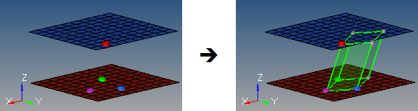
Figure 1.
- base node
- Select the node that defines the first corner on the bottom face.
- node 1
- Select the node that defines the corner of the bottom face that indicates the depth.
- node 2
- Select the node that defines the corner of the bottom face that indicates the width.
- The bottom face of the block is then completed by rotating a copy of the
triangle formed by these 3 nodes 180 degrees, and then matching the line
between node 1 and node 2 for each triangle to create a
parallelogram.
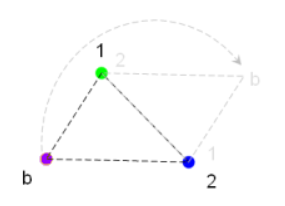
Figure 2. - Node 3
- Select the node that defines the corner of the top face that indicates the height and angle.
 Cylinder Full Subpanel
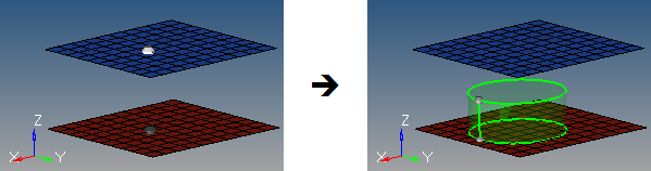
Figure 3.
- bottom center node
- Select the node that defines the center of the bottom cylinder face.
- vector between the bottom center and normal vector node
- Select the vector that defines the cylinder axis, thereby defining the
cylinder orientation. Note: This does not indicate the actual cylinder height.
- base radius
- Specify the radius of the top and bottom cylinder faces.
- height
- Specify the cylinder height.
 Cylinder Partial Subpanel
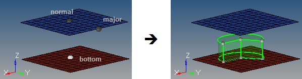
Figure 4.
- bottom center node
- Select the node that defines the center of the bottom cylinder face.
- vector between the bottom center and normal vector node
- Select the vector that defines the cylinder axis, thereby indicating the cylinder orientation. This does not indicate the actual cylinder height.
- vector between the bottom center and major vector node
- Select the vector that defines the zero-degree point of an arc defining the curved surface of the partial cylinder. This arc extends in a direction based on the normal vector using the right-hand rule, with its start angle and end angle specified relative to this vector.
- base radius
- Specify the radius of the top and bottom cylinder faces.
- height
- Specify the cylinder height.
- start angle
- Specify the angle that defines the starting arc angle, measured from the major vector node in a direction based on the normal vector using the right-hand rule.
- end angle
- Specify the angle that defines the ending arc angle, measured from the major vector node in a direction based on the normal vector using the right-hand rule.
- axis ratio
- Specify the percentage of the major vector.
- This value must be greater than zero and less than or equal to 1.0.
Values other than 1.0 create oval-shaped cylinders instead of circular
ones.
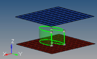
Figure 5. Axis Ratio Example. With a ratio of 0.5 the cone is half as wide as its length.
 Cone Full Subpanel
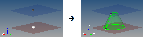
Figure 6. Cone Full Example. The cone is created with a top radius of 1.0; if the radius had been 0, it would taper to a point instead.
- bottom center node
- Select the node that defines the center of the bottom cone face.
- vector between the bottom center node and the normal vector node
- Select the vector that defines the cone axis, thereby indicating the cone orientation.
- top radius
- Specify the radius of the top cone face.
- base radius
- Specify the radius of the bottom cone face.
- height
- Specify the distance between the cone's base and its top.
 Cone Partial Subpanel
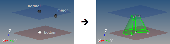
Figure 7.
- bottom center node
- Select the node that defines the center of the bottom cone face.
- vector between the bottom center node and the normal vector node
- Select the vector that defines the cone axis, thereby indicating the cone orientation.
- vector between the bottom center node and the major vector node
- Select the vector that defines the zero-degree point of an arc defining the curved surface of the partial cone. This arc extends in a direction based on the normal vector using the right-hand rule, with its start angle and end angle specified relative to this vector.
- top radius
- Specify the radius of the top cone face.
- base radius
- Specify the radius of the bottom cone face.
- height
- Specify the distance between the cone's base and its top.
- start angle
- Specify the starting arc angle, measured from the major vector node in a direction based on the normal vector using the right-hand rule.
- end angle
- Specify the ending arc angle, measured from the major vector node in a direction based on the normal vector using the right-hand rule.
- axis ratio
- Specify the percentage of the major vector.
- This value must be greater than zero and less than or equal to 1.
Decimal values create oval-shaped cones instead of circular ones.
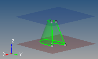
Figure 8.
 Sphere Center and Radius Subpanel
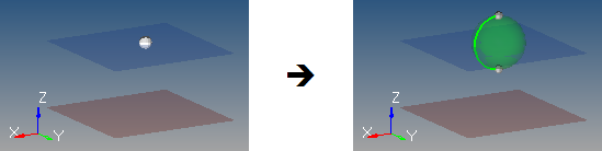
Figure 9.
- center node
- Select the node that defines the center of the sphere.
- radius
- Specify the sphere radius.
 Sphere Four Nodes Subpanel
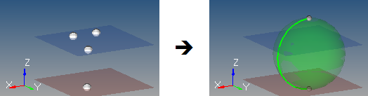
Figure 10.
The selected nodes cannot all be coplanar. The smallest sphere that passes through all four nodes is created. If more than four nodes are selected, only the four most recent are used.
 Torus Center and Radius Subpanel
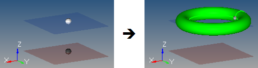
Figure 11.
- center node
- Select the node that defines the center of the torus.
- vector between the center node and the normal vector node
- Select the vector that defines the torus axis, thereby defining the torus orientation.
- major radius
- Specify the outside radius of the torus, measured from the center node.
- minor radius
- Specify the radius of the circular cross-section of the torus.
 Torus Three Nodes Subpanel
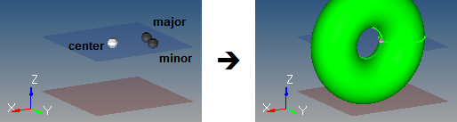
Figure 12.
- major center node
- Select the node that defines the absolute center of the torus.
- minor center node
- Select the node that defines the center of the circular cross-section of the torus.
- distance between the minor center node and the minor radius node
- Specify the distance that defines the radius of the circular cross-section of the torus.
The three nodes must define a plane and cannot be collinear. The circle defined on that plane by the minor center and radius is then spun around the major center to create the torus.
 Torus Partial Subpanel
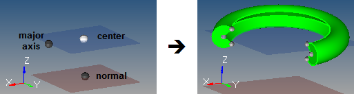
Figure 13. Torus with Partial Start and End Angles on Both the Major and Minor Radii. The partial major radius produces the broken/partial ring, while the partial minor radius produces the interior groove. The image of the torus is zoomed-in for better detail.
- center node
- Select the node that defines the absolute center of the torus.
- vector between the center node and the normal node
- Select the vector that defines the torus axis.
- vector from the center node to the major axis node
- Select the vector that completes the definition of the torus plane.
- major radius
- Specify the radius that defines the outside radius of the torus, measured from the center node.
- major start angle
- Specify the angle that defines the starting arc angle for the major circumference (ring), measured from the torus plane in a direction based on the torus axis using the right-hand rule.
- major end angle
- Specify the angle that defines the ending arc angle for the major circumference (ring), measured from the torus plane in a direction based on the torus axis using the right-hand rule.
- minor radius
- Specify the radius that defines the radius of the circular cross-section of the torus.
- minor start angle
- Specify the angle that defines the starting arc angle for the minor circumference (cross-section), measured from the mid-plane of the cross-section in a direction based on the cross-section centerline using the right-hand rule.
- minor end angle
- Specify the angle that defines the ending arc angle for the minor circumference (cross-section), measured from the mid-plane of the cross-section in a direction based on the cross-section centerline using the right-hand rule.
 Bounding Surfaces Subpanel
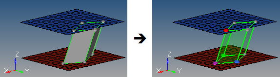
Figure 14.
- surfaces
- Select the surfaces that define the continuous, closed shell. The surface selection must be completely closed; if the surface selection contains any free edges or gaps, a solid cannot be created.
- auto select solid surfaces
- Select a single surface, then automatically select the other surfaces that form a continuous shell.
- create in
- Choose a method for organizing the resulting solid body components.
- current component
- Organize the new solids and the selected surfaces to the current component.
- surfs component
- Organize the new solids to the same component that the selected surfaces already belong to. If the input surfaces are in different components, the result is not predictable.
 Spin Subpanel
Figure 15. Spin Example. The selected surface spins 120 degrees around the X axis at the base node, in the positive direction.
- surfaces
- Select the surfaces to spin.
- merge solids at shared edges
- Create a single solid with merged faces created at the shared edge locations.
- create in
- Choose a method for organizing the resulting solids component.
- current component
- Organize the new solids and the selected surfaces to the current component.
- surfs component
- Organize the new solids to the same component that the selected surfaces already belong to.
- plane/vector selection
- Select the plane/vector that defines the rotation axis.
- start angle
- Specify initial angle of the solid formed by the spin, measured about the axis of rotation using the right-hand rule. The selected surfaces will be rotated this many degrees before HyperMesh extrudes the solid from them by an additional number of degrees determined by the difference between the start angle and end angle. Thus, each angle determines the position of one face along the arc of rotation, and therefore the difference between start and end angles determines the thickness of the solid through the arc.
- end angle
- Specify the final angle through with the surfaces are spun, thus determining the solid's thickness along the arc of rotation. The angle is measured about the axis of rotation using the right-hand rule. The total angle is given by (end angle - start angle).
- spin direction
- Define the direction of the spin.
- spin +
- Defined using the right-hand rule around the axis of rotation and uses the start angle and end angle values as specified.
- spin -
- Defined in the opposite direction and uses the negative of the specified start angle and end angle values.
 Drag Along Vector Subpanel
Figure 16.
- surfaces
- Select the surfaces to drag.
- plane/vector selector
- Select the plane/vector to define the drag direction. If a vector is defined or selected, this represents the positive drag direction. If a plane is defined, the plane normal represents the positive drag direction.
- keep connectivity
- Maintain the connectivity of the input surfaces to any attached surfaces. If the input surface is part of a solid, this must be enabled.
- merge solids at shared edges
- Create a single solid with merged faces created at the shared edge locations.
- create in
- Choose a method for organizing the resulting solids component.
- current component
- Organize the new solids and the selected surfaces to the current component.
- surfs component
- Organize the new solids to the same component that the selected surfaces already belong to.
- distance
- Specify the length to drag the surface along the vector.
- drag direction
- Define the direction of the drag.
- drag +
- Defined using the specified vector direction.
- drag -
- Defined in the opposite direction.
- inflate
- Create a new solid from surfaces, by extruding the surface in both directions by half of the specified thickness.
 Drag Along Line Subpanel
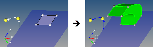
Figure 17.
- lines/node list
- Select the lines or node list to drag.
- lines
- Select the lines that the drag will follow. This can also be a series of connected lines.
- node list
- Select the node(s) that the line will first be fit through.
- merge solids at shared edges
- Create a single solid with merged faces created at the shared edge locations.
- create in
- Choose a method for organizing the resulting solids component.
- current component
- Organize the new solids and the selected surfaces to the current component.
- surfs component
- Organize the new solids to the same component that the selected surfaces already belong to.
- frame mode
- Choose a method for how the surfaces are translated and rotated during
the drag.
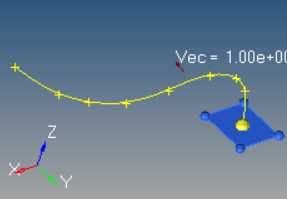
Figure 18. Starting Model- fixed frame
- Only translate the surfaces during the drag, do not rotate
the surfaces.
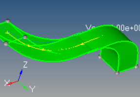
Figure 19. - line tangent
- In addition to the translation of the fixed frame option,
rotate the surfaces in the same way that the tangent of the
line list rotates.
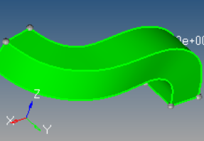
Figure 20. - frenet frame
- In addition to the translation and rotation of the line
tangent option, rotate the surfaces around the line list
tangent axis in the same way as the curvature vector
rotates.Note: Does not work well when the curvature of the line is not smooth or there are large jumps.
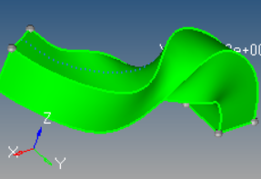
Figure 21.
- reference node and transformation plane
-
- S
- Start of drag line, which is the closest end of the line to the surface vertices.
- T
- Tangent of drag line at S.
- R
- Reference node.
- Translate the drag line prior to the drag. By default, R=S.
If a different S is specified, the line list is translated
by the vector defined from S to R.
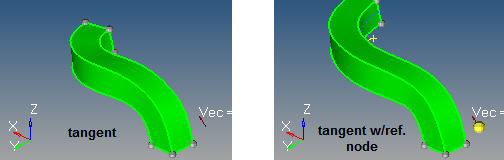
Figure 22. - B
- Base node of the transformation plane.
- N
- Normal vector of the transformation plane.
- transformation plane
- Translate and rotate the input surfaces prior to the drag.
By default, no transformation occurs (B=R and N=T). If
specified, the surfaces are translated by the vector defined
from R to B, and are rotated from N to T.
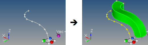
Figure 23.
- drag direction
- Define the direction of the drag.
- drag +
- Defined at the start of drag line, which is the closest end of the line to the surface vertices.
- drag -
- Defined in the opposite direction.
 Drag Along Normal Subpanel
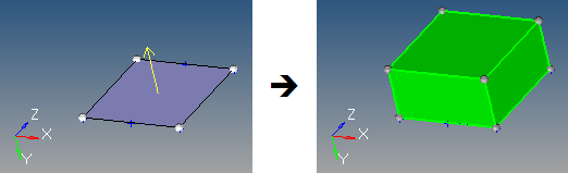
Figure 24. Drag Along Normal Example. The yellow arrow displays once the surface is selected, and indicates the surface normal.
- surfaces
- Select the surface(s) to drag.
- keep connectivity
- Maintain the connectivity of the input surfaces to any attached surfaces. If the input surface is part of a solid, this must be enabled.
- merge solids at shared edges
- Create a single solid with merged faces created at the shared edge locations.
- create in
- Choose a method for organizing the resulting solids component.
- current component
- Organize the new solids and the selected surfaces to the current component.
- surfs component
- Organize the new solids to the same component that the selected surfaces already belong to.
- distance
- Specify the length to drag the surfaces along it normal.
- drag direction
- Define the direction of the drag.
- drag +
- Defined using the surface normal direction.
- drag -
- Defined in the opposite direction.
 Ruled Linear Subpanel
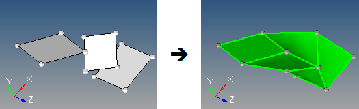
Figure 25.
- surface list
- Select the surface list to use.
- create ring solid
- Consider the first and last surfaces in the list as a pair in order to form a closed loop solid.
- split solid at shared surfaces
- Split the solid at each of the input surfaces to create multiple solids with shared surfaces.
- create in
- Choose a method for organizing the resulting solids component.
- current component
- Organize the new solids and the selected surfaces to the current component.
- surfs component
- Organize the new solids to the same component that the selected surfaces already belong to.
- link type
- Select whether user-defined links are used to provide better
interpolation and shape control.
- default
- Ignore user-defined links or guiding lines/surfaces.
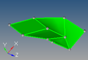
Figure 26. - select links
- Define node/point links.
- Node/point links are input as pairs since a link between
input surfaces is specified by its two end points/nodes.
Furthermore, a pair may not skip any surface in between. For
instance, if surfaces 1, 2, 3 and 4 are defined in that
order as the input surface list, a link can be defined from
surface 2 to 3 but not from surface 2 to 4. If such a link
is detected, it is ignored. One point/node may be linked to
multiple points/nodes, which results in the creation of
triangular surfaces. Node/point links show graphically as a
white line between the pairs, with an L at the line center.
To disable a pre-defined link, right-click the L graphic. To
re-enable a disabled link, left-click the L graphic.
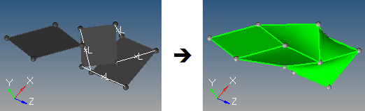
Figure 27.
 Ruled Smooth Subpanel
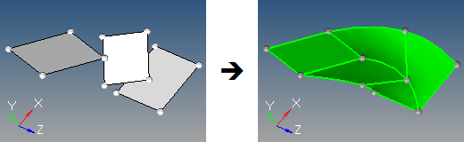
Figure 28.
- surface list
- Select a surface list to use.
- create ring solid
- Consider the first and last surfaces in the list as a pair in order to form a closed loop solid.
- split solid at shared surfaces
- Split the solid at each of the input surfaces to create multiple solids with shared surfaces.
- create in
- Choose a method for organizing the resulting solids component.
- current component
- Organize the new solids and the selected surfaces to the current component.
- surfs component
- Organize the new solids to the same component that the selected surfaces already belong to.
- link type
- Select whether user-defined links are used to provide better
interpolation and shape control.
- default
- Ignore user-defined links or guiding lines/surfaces.
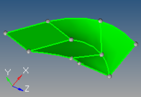
Figure 29. - define links
- Define node/point links. Node/point links are input as pairs
since a link between input surfaces is specified by its two
end points/nodes. Furthermore, a pair may not skip any
surface in between. For instance, if surfaces 1, 2, 3 and 4
are defined in that order as the input surface list, a link
can be defined from surface 2 to 3 but not from surface 2 to
4. If such a link is detected, it is ignored. One point/node
may be linked to multiple points/nodes, which results in the
creation of triangular surfaces. Node/point links show
graphically as a white line between the pairs, with an L at
the line center. To disable a pre-defined link, right-click
the L graphic. To re-enable a disabled link, left-click the
L graphic.
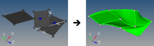
Figure 30. - Define guiding lines and guiding surfaces. Guiding lines are
used to indicate part of the boundary of the final
interpolated solid. If more than one guiding line is
selected, the edges of the solid between these lines are
obtained by smoothly interpolating the lines. If a guiding
line extends beyond the input surfaces, that part of the
line is ignored.
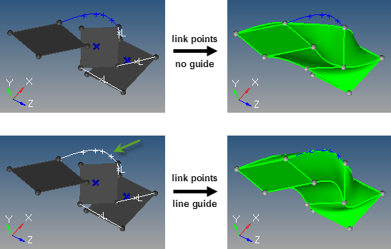
Figure 31. Link Points
In the case of a surface with a scratch, if one of the internal points of the scratch is not linked to another surface at its boundary, this scratch is treated as if it is not part of the boundary, that is, as if it does not exist. If the scratch is linked upward but not downward, then is it considered a part of the boundary while constructing surfaces between its level and the level above, but it is ignored while constructing boundary with the surface below.
All the surfaces at each level must have the same number of internal loops, if any. Currently, only one internal loop at each level is supported. Cases with more than one internal loop will generate solids, but the matching between loops may not be desirable.