Solid Edit Panel
Use the Solid Edit panel to modify solid entities.
Location: Geom page.
For example, you can trim and/or split solids, as well as merge solids into a single entity using the Solid Edit panel.
Trim with Nodes Subpanel
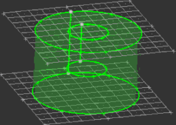
Use the Trim with Nodes subpanel to trim solids based on nodes that you select. The nodes must define an enclosed cross-sectional surface, but this surface need not be planar.
Multiple solids can be trimmed using the same set of nodes; each solid is trimmed according to the surface defined by those nodes, provided that this surface intersects each solid. However, HyperMesh only creates new surfaces within the solids. For example, if your nodes define a large plane that intersects two cubes, HyperMesh will only create surfaces within the cubes (and thus trim them). It will not create a single surface filling the entire area enclosed by the nodes.
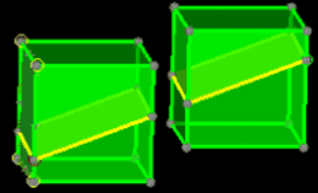
Figure 1. 4 Nodes: 2 at the Outer Edge
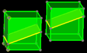
Figure 2. Single Cut
| Option | Action |
|---|---|
| solids / surfs selector | Choose a method for
selecting solids.
|
| nodes list / points selector | Choose a method for
defining your 2D cutting plane (or non-planar surface).
|
| extend trimmer | Extend the trimming operation beyond the boundaries of the nodes, or lines that you used to define it. |
Trim with Lines Subpanel
Use the Trim with Lines subpanel to select lines from your model to define the edges of a trim plane.
- Cut Lines
- Create a cut through the solid along a line that you draw.
- Bounding Lines
- Choose lines from the model geometry that define a plane or other 2D area. The solid is then cut along this plane.
- Sweep Lines
- Select lines in your model and then extending those lines to create 2D cutting surfaces. Thus, you can "sweep" the lines through your model, either along a specified vector or to one or more end points, to define the cuts.
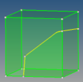
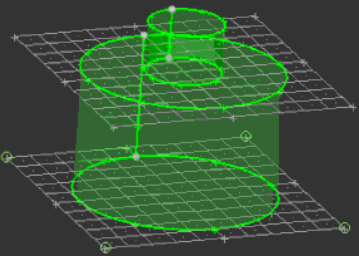
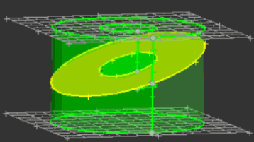
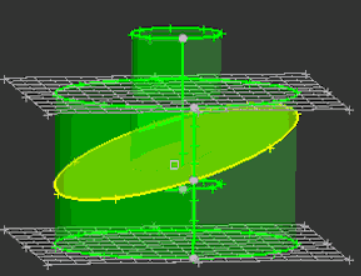
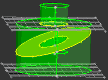
Figure 3. Solid Entity Cut along the Line Segment(s) Laid Down
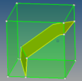
Figure 4. Solid Entity Cut along the Line Segment(s) Laid Down, Rotated Slightly
| Option | Action |
|---|---|
| with cut line: solids selector | Choose a method for
selecting solids.
Note: Regardless of the method, you are still selecting solid
entities to trim.
|
| drag a cut line | Draw a cut line.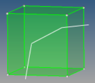 Figure 5. |
| smooth line | Create a curved line
that passes through the points you specify.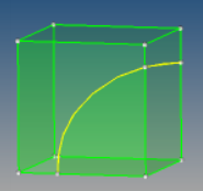 Figure 6. |
| close line | Create a closed loop,
automatically connecting the first and last points that you
specify.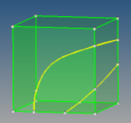 Figure 7. |
| with bounding lines: solids selector | Choose a method for
selecting solids.
Note: Regardless of the method, you are still selecting solid
entities to trim.
|
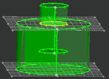
| with bounding lines:lines selector | Select the lines in
your model that define the desired cutting plane. 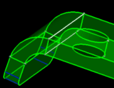 Figure 8. Lines Selected. The top and bottom lines are selected (white).  Figure 9. Solid Split. The selected solids are split along the plane bounded by the chosen lines. |
| with bounding lines: extend trimmer | Extend the trimming operation beyond the boundaries of the nodes, or lines that you used to define it. |
| with sweep lines: solids selector | Choose a method for
selecting solids.
Note: Regardless of the method, you are still selecting solid
entities to trim.
|
| with sweep lines:lines selector | Select the lines to
sweep. These lines, plus their destination, determine the shape
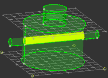
and orientation of the cut. Click trim. HyperMesh sweeps the selected line(s) along the specified vector or through the specified nodes, splitting the entity along this path (which is frequently not planar when using "end" nodes). 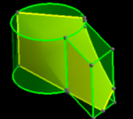 Figure 10. Sweep All Enabled. Surfaces sweep past the nodes. |
| with sweep lines:sweep to | Choose between 1 or 2 end nodes or sweeping by a vector. |
| with sweep lines:Sweep all / Option field / N2 - N1 |
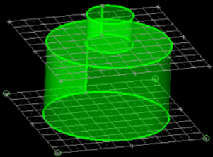
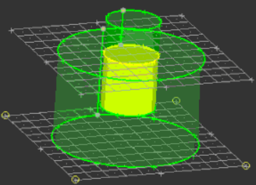
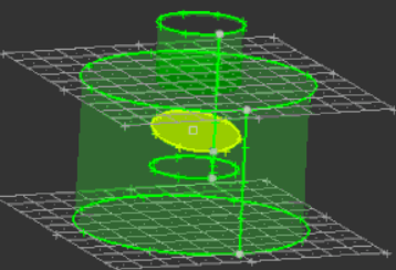
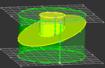
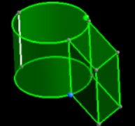 Figure 11. With Sweep Lines Set to N2 - N1. The line behind the cylinder is selected, and the green and blue nodes are N1 and N2. |
Trim with Plane/Surf Subpanel
Use the Trim with Plane/Surf subpanel to trim solid geometries using a plane or other trimming surface.
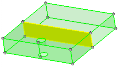
Figure 12.
This process uses the *body_splitmerge_with_plane command or *trim_solids_by_surfaces command, as appropriate.
| Option | Action |
|---|---|
| with plane: solids / surfs | Select the entities to
trim. If you pick surfaces, the related solids are selected.
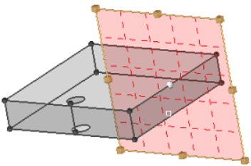
When trim with planes is enabled, a fill cuts mode is turned on and used. Fill cuts is a special mode of surface trimming. A virtual trimmer surface is created and used to calculate and create new edges on selected surfaces. An attempt is made to insert pieces of this trimmer surface into the body when trimming of the trimmer itself by selected surfaces creates closed loops and thus cuts off those pieces. This is used to simulate solid trimming in cases when you cannot, or do not want to, create solids, but still wants to make solid-like cuts. This mode is not intended when selected surfaces are solid surfaces themselves. When attempting to insert pieces of a trimmer surface into a solid body, you may also need to manually select other surfaces in order to avoid topologically invalid results. If you do not make this selection completely correctly, the expected result will be undefined. |
| with plane: | Choose a method for
defining your cutting plane.
|
| with surfs: solids / surfs (switch) | Choose a method for
selecting solids.
Note: Regardless of the method, you are still selecting solid
entities to trim.
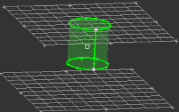
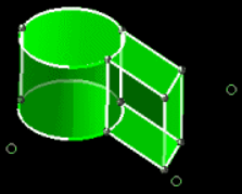 Figure 14. Selected Solid. The entire selected structure is a single solid. |
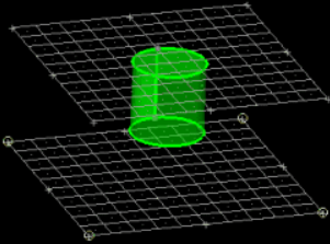
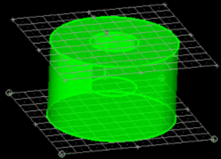
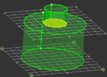
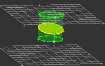
| with surfs: surfs (standalone selector) | Use the surfs selector
to select surfaces to extend.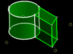 Figure 15. Solid Selected. The outer curve of the cylinder is selected. 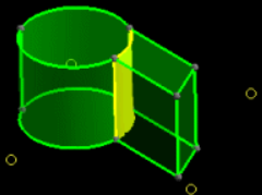 Figure 16. Solid Split. When you click trim, the cylindrical surface extends to split the solid. |
| with surfs: extend trimmer | Extend the trimming operation beyond the boundaries of the input surface when the surface is not part of any selected solid. If the input surface is part of a selected solid, the trimmer is always extended in order for the operation to be relevant, regardless of the status of this option in the application. |
Merge Subpanel
Use the Merge subpanel to join solid entities that are currently separated by a narrow gap.
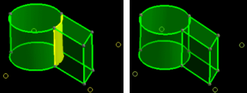
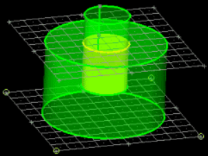
Figure 17. . The dividing surface (yellow) becomes shared (green) after merging.
You can merge solids in two ways: either select solids to merge, or select intervening surfaces to remove.
| Option | Action |
|---|---|
| to be merged: solids | Select the solids to merge. |
| to be merged: remove scratches | If one or more faces of your model include scratches (surface features on the face which do not completely divide the face), enable remove scratches to remove them during the merge process. |
| merge by removal: surfs | Select the surfaces to remove. |
Detach Subpanel
Use the Detach subpanel to detach (separate) a selected solid from neighboring solids with which it shares one or more common faces (drawn in yellow).
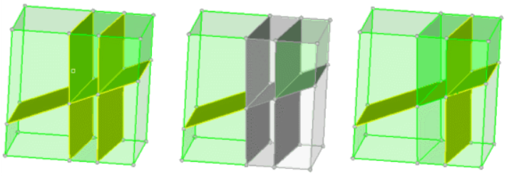
Figure 18. Attached Solids. From left to right this series shows 6 attached solids; selection of 4 of the solids; and the subsequently detached solids. Notice that the selected solids weren't detached from each other, only from the non-selected solids.
Use the solids selector to select solids to detach from each other.
Boolean Subpanel
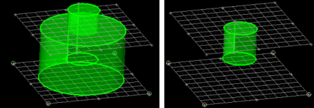
Figure 19. . Only the portion shared by both cylinders is retained.
| Option | Action |
|---|---|
| simple (combine all) | Perform a simple combination of solids. |
| advanced | Perform a complex boolean operation. |
| A: solids | Select one group of solids (usually the ones which you want to add to or subtract from). |
| B: solids | Select the other group of solids (usually the ones that you wish to modify the ones in group A). |
| swap A and B | Invert the selection of A and B. |
| operation: | Choose the type of
Boolean operation to perform.
Note: Advanced operations, except for A (keep A parts),
cannot be performed without using one of the combine through
options.
|
| combine through: | The effects of these
options depend on the operation performed, and not all options
are available for every operation.
|