/FAIL/PUCK
Block Format Keyword Describes the Puck failure model.
Format
| (1) | (2) | (3) | (4) | (5) | (6) | (7) | (8) | (9) | (10) |
|---|---|---|---|---|---|---|---|---|---|
| /FAIL/PUCK/mat_ID/unit_ID | |||||||||
| Ifail_sh | Ifail_so | ||||||||
| (1) | (2) | (3) | (4) | (5) | (6) | (7) | (8) | (9) | (10) |
|---|---|---|---|---|---|---|---|---|---|
| fail_ID |
Definitions
| Field | Contents | SI Unit Example |
|---|---|---|
| mat_ID | Material identifier (Integer, maximum 10 digits) |
|
| unit_ID | Unit Identifier (Integer, maximum 10 digits) |
|
| Longitudinal tensile strength Default = 1030 (Real) |
||
| Transverse tensile strength Default = 1030 (Real) |
||
| Shear strength Default = 1030 (Real) |
||
| Longitudinal compressive
strength Default = 1030 (Real) |
||
| Transverse compressive
strength Default = 1030 (Real) |
||
| Failure envelope factor 12 (+) Default = 0 (Real) |
||
| Failure envelope factor 12 (-) Default = 0 (Real) |
||
| Failure envelope factor 22 (-) Default = 0 (Real) |
||
| Dynamic time relaxation 5 Default = 1030 (Real) |
||
| Ifail_sh | Shell failure model flag
(Integer) |
|
| Ifail_so | Solid failure model flag
(Integer) |
|
| fail_ID | Failure criteria
identifier
4 (Integer, maximum 10 digits) |
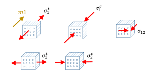
Example (Composite)
Strength ( ) are taken from following tests. m1 is fiber direction.
#RADIOSS STARTER
#---1----|----2----|----3----|----4----|----5----|----6----|----7----|----8----|----9----|---10----|
/UNIT/1
unit for mat and failure
#              MUNIT               LUNIT               TUNIT
                   g                  mm                  ms
#---1----|----2----|----3----|----4----|----5----|----6----|----7----|----8----|----9----|---10----|
#-  1. MATERIALS:
#---1----|----2----|----3----|----4----|----5----|----6----|----7----|----8----|----9----|---10----|
/MAT/COMPSH/1/1
composite example
#              RHO_I
               .0015
#                E11                 E22                NU12     Iform                           E33
              114000                9650                .025         0                             0
#                G12                 G23                 G31              EPS_f1              EPS_f2
                6000                6000                6000                   0                   0
#             EPS_t1              EPS_m1              EPS_t2              EPS_m2                dmax
                   0                   0                   0                   0                   0
#              Wpmax               Wpref      Ioff                         ratio
                   0                   0         4                             0
#                  b                   n                fmax
                   0                   0                   0
#            sig_1yt             sig_2yt             sig_1yc             sig_2yc               alpha
                1E30                1E30                1E30                1E30                   0
#           sig_12yc            sig_12yt                c_12          Eps_rate_0       ICC
                1E30                1E30                   0                   0         0
#          GAMMA_ini           GAMMA_max               d3max
                   0                   0                   0
#  Fsmooth                Fcut
         0                   0
/FAIL/PUCK/1/1
#           Sigma1_T            Sigma2_T            Sigma_12            Sigma1_C            Sigma2_C
                1720                55.2                 103                 765                 503
#               P+12                P-12                P-22             Tau_max  Ifail_sh  Ifail_so
                   0                   0                   0                .005         1         0
#---1----|----2----|----3----|----4----|----5----|----6----|----7----|----8----|----9----|---10----|
#enddata
#---1----|----2----|----3----|----4----|----5----|----6----|----7----|----8----|----9----|---10----|
Comments
- This failure model is available for Shell and Solid.
- The failure mode criteria is written as:
- Fiber fraction failure:Tensile fiber failure mode:
(1) Compressive fiber failure mode:(2)
- Inter fiber failure:Mode A if :
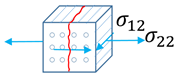
Figure 1.(3) Mode C if :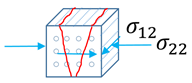
Figure 2.(4) Mode B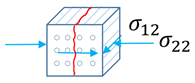
Figure 3.
If the damage parameter is , the stresses are decreased by using an exponential function to avoid numerical instabilities. A relaxation technique is used by decreasing the stress gradually:(5) With,(6) and
Where,- Time
- Start time of relaxation when the damage criteria is assumed
- Time of dynamic relaxation
- Stress at the beginning of damage
- Fiber fraction failure:
- The damage value, D is
. The status for fracture is:
- Free, if
- Failure, if
With . This damage value shows with /ANIM/BRICK/DAMA or /ANIM/SHELL/DAMA.
- The fail_ID is used with /STATE/BRICK/FAIL and /INIBRI/FAIL. There is no default value. If the line is blank, no value will be output for failure model variables in the /INIBRI/FAIL (written in .sta file with /STATE/BRICK/FAIL option).
- After the failure criterion is reached, the value determines a period of time when the stress in the failed element is gradually reduced to zero. When the stress reaches 1% of stress value at the start of failure, the element is deleted. This is necessary to avoid instabilities coming from a sudden element deletion and a failure “chain reaction” in the neighboring elements. Even if the failure criterion is reached, the default value of results in no element deletion. Therefore, it is recommended to define 10 times larger than the simulation time step.