/FAIL/FLD
Block Format Keyword Describes the forming limit.
Format
| (1) | (2) | (3) | (4) | (5) | (6) | (7) | (8) | (9) | (10) |
|---|---|---|---|---|---|---|---|---|---|
| /FAIL/FLD/mat_ID/unit_ID | |||||||||
| fct_ID | Ifail_sh | I_marg | fct_ID adv | Rani | Dadv | Istrain | Ixfem | ||
| (1) | (2) | (3) | (4) | (5) | (6) | (7) | (8) | (9) | (10) |
|---|---|---|---|---|---|---|---|---|---|
| Factor_Marginal | Factor_loosemetal | ||||||||
| (1) | (2) | (3) | (4) | (5) | (6) | (7) | (8) | (9) | (10) |
|---|---|---|---|---|---|---|---|---|---|
| fail_ID |
Definitions
| Field | Contents | SI Unit Example |
|---|---|---|
| mat_ID | Material identifier (Integer, maximum 10 digits) |
|
| unit_ID | Unit Identifier (Integer, maximum 10 digits) |
|
| fct_ID | Function identifier (FLD
diagram). (Integer) |
|
| Ifail_sh | Shell failure flag.
(Integer) If Ixfem =0: failure - element deleted. If Ixfem =1: failure - element cracked. 2 |
|
| fct_IDadv | Failure advancement diagram function
identifier. Only active, if Ixfem=1. 3 (Integer) |
|
| Istrain | Engineering / True input strain flag.
(Integer) |
|
| Rani | Average anisotropy factor. Default = 1.0 (Real, positive) |
|
| Dadv | Criterion for crack advancement. Only active, if Ixfem=1. 3 (Real, between 0 and 1) Default = 0.5, if fct_IDadv is not defined (for backward compatibility) Default = 1.0, if fct_IDadv is defined |
|
| Ixfem | XFEM flag (for
/PROP/SHELL, /PROP/SH_SANDW, and
/PROP/TYPE51 properties only).
(Integer) |
|
| I_marg | Marginal value flag. 5
(Integer) |
|
| Factor_Marginal | Marginal FLD curve calculation value.
5 Default = 0.10 (Real, positive) |
|
| Factor_Loosemetal | Loose metal curve calculation value.
5 Default = 0.02 (Real, positive) |
|
| fail_ID | Failure criteria
identifier. 4 (Integer, maximum 10 digits) |
Example (element deleted)
#RADIOSS STARTER
#---1----|----2----|----3----|----4----|----5----|----6----|----7----|----8----|----9----|---10----|
/UNIT/1
unit for mat
#              MUNIT               LUNIT               TUNIT
                  Mg                  mm                   s
#---1----|----2----|----3----|----4----|----5----|----6----|----7----|----8----|----9----|---10----|
#-  1. MATERIALS:
#---1----|----2----|----3----|----4----|----5----|----6----|----7----|----8----|----9----|---10----|
/MAT/PLAS_JOHNS/4/1
metal
#              RHO_I
              2.8E-9                   0
#                  E                  Nu
               60000                  .3
#                  a                   b                   n           EPS_p_max            SIG_max0
                 270                 450                  .6                   0                   0
#                  c           EPS_DOT_0       ICC   Fsmooth               F_cut               Chard
                   0                   0         0         0                   0                   0
#                  m              T_melt              rhoC_p                 T_r
                   0                   0                   0                   0
/FAIL/FLD/4/1
#  Func_id  Ifail_sh   I_marg Fct_ID_adv               R_ani                Dadv   Istrain     Ixfem
      1012         1         0         0                   0                   0         0         0
#---1----|----2----|----3----|----4----|----5----|----6----|----7----|----8----|----9----|---10----|
/FUNCT/1012
FLD diagram
#                  X                   Y
                -0.7                0.90
                -0.4                0.60
                -0.3                0.50
                -0.2                0.40
               -0.15                0.35
                -0.1                0.30
               -0.05                0.29
               -0.03                0.28
                 0.0                0.28
                0.05                0.33
                 0.1                0.36
                 0.2                0.39
                 0.3                0.42
                 0.4                0.45
#---1----|----2----|----3----|----4----|----5----|----6----|----7----|----8----|----9----|---10----|
#enddata
#---1----|----2----|----3----|----4----|----5----|----6----|----7----|----8----|----9----|---10----|
Example (element cracked)
#RADIOSS STARTER
#---1----|----2----|----3----|----4----|----5----|----6----|----7----|----8----|----9----|---10----|
/UNIT/1
unit for mat
#              MUNIT               LUNIT               TUNIT
                  Mg                  mm                   s
#---1----|----2----|----3----|----4----|----5----|----6----|----7----|----8----|----9----|---10----|
#-  1. MATERIALS:
#---1----|----2----|----3----|----4----|----5----|----6----|----7----|----8----|----9----|---10----|
/MAT/PLAS_JOHNS/4/1
metal
#              RHO_I
              2.8E-9                   0
#                  E                  Nu
               60000                  .3
#                  a                   b                   n           EPS_p_max            SIG_max0
                 270                 450                  .6                   0                   0
#                  c           EPS_DOT_0       ICC   Fsmooth               F_cut               Chard
                   0                   0         0         0                   0                   0
#                  m              T_melt              rhoC_p                 T_r
                   0                   0                   0                   0
/FAIL/FLD/4/1
#  Func_id  Ifail_sh   I_marg Fct_ID_adv               R_ani                Dadv   Istrain     Ixfem
      1012         1         0      1013                   0                 0.6         0         1
#---1----|----2----|----3----|----4----|----5----|----6----|----7----|----8----|----9----|---10----|
/FUNCT/1012
FLD diagram - Initiation
#                  X                   Y
                -0.7                0.90
                -0.4                0.60
                -0.3                0.50
                -0.2                0.40
               -0.15                0.35
                -0.1                0.30
               -0.05                0.29
               -0.03                0.28
                 0.0                0.28
                0.05                0.33
                 0.1                0.36
                 0.2                0.39
                 0.3                0.42
                 0.4                0.45
#---1----|----2----|----3----|----4----|----5----|----6----|----7----|----8----|----9----|---10----|
/FUNCT/1013
failure advancement diagram
#                  X                   Y
                -0.7                0.90
                -0.4                0.60
                -0.3                0.50
                -0.2                0.40
               -0.15                0.35
                -0.1                0.30
               -0.05                0.29
               -0.03                0.28
                 0.0                0.28
                0.05                0.33
                 0.1                0.36
                 0.2                0.39
                 0.3                0.42
                 0.4                0.45
#---1----|----2----|----3----|----4----|----5----|----6----|----7----|----8----|----9----|---10----|
#enddata
#---1----|----2----|----3----|----4----|----5----|----6----|----7----|----8----|----9----|---10----|
Comments
- This failure model is available for Shell only.
- XFEM formulation
(Ixfem=1) is only compatible with
Belytchko (Ishell=1 or 2), Ishell=3 or 4 and QEPH (Ishell=24) shell elements. If XFEM flag is activated
(Ixfem=1), the failure criteria will lead
to element cracking instead of element or layer deletion.Two XFEM options are available: mono-layer and multi-layer. The XFEM option depends on the property type associated to the failure criterion applied to the material identifier:
- If /PROP/SHELL (TYPE1) is used, then mono-layer XFEM will be
applied.
In this case, the whole element thickness is considered as a single layer. The failure criterion is calculated in each integration point, but only one crack can appear in this element. This approach is compatible with all values of the shell flag (Ifail_sh=1 or 2). The crack direction is determined by the principal constraints in the last failed integration point.
- If /PROP/SH_SANDW (TYPE11) is used, then multi-layer
XFEM will be applied.
In this case, each integration point over thickness is considered as a distinct layer. The failure criterion is calculated separately and the crack direction may be different in each layer. Crack direction in each layer will independently propagate from one element to another. Multi-layer XFEM is not compatible with Ifail_sh=1. Its value will be automatically set to Ifail_sh=2 in this case.
- If /PROP/TYPE51 is used, then multi-layer XFEM will be applied
and the separate cracks may appear in each layer and propagate independently from one
element to another. Thus, crack directions and patterns will be different in each
layer. The failure criterion is calculated separately in each integration point and
crack will propagate when all the integration points fail within a layer. Multi-layer
XFEM is not compatible with
Ifail_sh=1. Its value will be
automatically set to Ifail_sh=2.Warning: Mono-layer and multi-layer XFEM formulations cannot be mixed in the same model, yet. The choice between them must be made for the whole model.
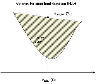
Figure 1.
- If /PROP/SHELL (TYPE1) is used, then mono-layer XFEM will be
applied.
- When the Ixfem option is used, a supplementary criterion is available for crack advancement, which may be different from the one used for the failure initialization. It will be used for elements with an existing crack tip at their border. If fct_IDadv is defined, Dadv is used as a scale factor for this function to obtain the advancement failure value. If fct_IDadv is not defined, the original FLD diagram (fct_ID) is used with the Dadv scale factor to obtain this value.
- The fail_ID is used with /STATE/BRICK/FAIL and /INIBRI/FAIL. There is no default value. If the line is blank, no value will be output for failure model variables in the /INIBRI/FAIL (written in .sta file with /STATE/BRICK/FAIL option).
- The inputs Rani, Factor_Marginal, and Factor_Loosemetal are only used for animation output /ANIM/SHELL/FLDZ to define FLD.