/FAIL/ALTER
Block Format Keyword An advanced nonlinear stress-based failure criteria for glass applications such as a windshield.
The failure stress is described by parameters defining micro-cracks and crack propagation speed. With the X-FEM approach, the stress is set to zero perpendicular to the crack direction.
Format
| (1) | (2) | (3) | (4) | (5) | (6) | (7) | (8) | (9) | (10) |
|---|---|---|---|---|---|---|---|---|---|
| /FAIL/ALTER/mat_ID/unit_ID | |||||||||
| Exp_n | V0 | Vc | Ncycles | Irate | mode | ||||
| Cr_foil | Cr_air | Cr_core | Cr_edge | grsh4N | grsh3N | ||||
| KIC | KTH | Rlen | |||||||
| (1) | (2) | (3) | (4) | (5) | (6) | (7) | (8) | (9) | (10) |
|---|---|---|---|---|---|---|---|---|---|
| fail_ID |
Definitions
| Field | Contents | SI Unit Example |
|---|---|---|
| mat_ID | Material identifier (Integer, maximum 10 digits) |
|
| unit_ID | Unit Identifier (Integer, maximum 10 digits) |
|
| Exp_n | Crack growth exponent for subcritical
crack growth. Default = 16.0 (Real) |
|
| V0 | Crack growth velocity for subcritical
crack growth at KIC. Default = 0.0 (Real) |
|
| Vc | Maximum crack propagation velocity
glass. Default = 0.0 (Real) |
|
| Ncycles | Stress filtering period in cycles. Only
used when Irate=0. 2
(Integer) |
|
| Irate | Stress rate filtering method.
(Integer) |
|
| mode | Flag to switch failure propagation
models between neighbor elements.
(Integer) |
|
| Cr_foil | Crack depth at bottom surface. Default = 0.0 (Real) |
|
| Cr_air | Crack depth at top surface. Default = 1.0 (Real) |
|
| Cr_core | Crack depth in between bottom and
surface integration points. Default = 1.0 (Real) |
|
| Cr_edge | Crack depth at the edge elements of
windshield. Default = 1.0 (Real) |
|
| grsh4N | (Optional) Group identifier for 4 node
edge shell elements. Default = 0 (Integer) |
|
| grsh3N | (Optional) Group identifier for 3 node
edge shell elements. Default = 0 (Integer) |
|
| KIC | Fracture toughness. Default = 0.0 (Real) |
|
| KTH | Fatique threshold. Default = 0.0 (Real) |
|
| Rlen | Reference length. Default = 1.0 (Real) |
|
| fail_ID | Failure criteria
identifier. 9 (Integer, maximum 10 digits) |
Comments
- This failure criteria is using the maximum stress as failure criterion. It is computed based on the strength of the material determined by initial cracks and the crack propagation velocity. Depending on mode switch flag, different failure propagation models between neighbor elements may be used.
- When
Irate=0, an exponential moving average filter is
used, and the filtered stress is:
(1) Where, - This failure model is compatible only with under-integrated shell elements (Ishell =24 and Ish3n =2 are recommended) and not compatible fully integrated shells. Also, although there is no restriction of the shell property that can be used, it is only compatible with one layer shell models.
- The elements defined in the groups grsh4N and grsh3N should be along the edge of the windshield and will receive specific failure weakening.
- This failure model is applied to shell
elements that sandwich a polyvinyl butyral (PVB) solid element layer using coincident
nodes. The entire assembly models a windshield.

Figure 1. Windshield Finite Element Model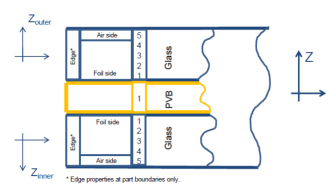
Figure 2. Windshield Model - Entire Assembly - The shell elements using this failure model should be oriented so their normals point away the from the middle PVB.
- The shell elements should have an offset applied to correctly model bending. This can be done using /PROP/TYPE51 Ipos=4.
- The fracture limit depends on the location and the fracture state of surrounding elements. 1
- The fail_ID is used with /STATE/BRICK/FAIL and /INIBRI/FAIL and /PERTURB/FAIL/BIQUAD. There is no default value. If the line is blank, no value will be output for failure model variables in the /INIBRI/FAIL (written in .sta file with /STATE/BRICK/FAIL for brick and with /STATE/SHELL/FAIL for shell).