/FAIL/BIQUAD
Block Format Keyword This failure model uses a simplified nonlinear, strain-based, failure criteria with linear damage accumulation. The failure strain is described by two parabolic functions calculated using curve fitting from up to 5 user-defined failure strains.
A perturbation of the failure limit for each element can be activated using /PERTURB/FAIL/BIQUAD. This failure criteria is developed in a partnership with Christian Cremer from Ford.
Format
| (1) | (2) | (3) | (4) | (5) | (6) | (7) | (8) | (9) | (10) |
|---|---|---|---|---|---|---|---|---|---|
| /FAIL/BIQUAD/mat_ID/unit_ID | |||||||||
| c1 | c2 | c3 | c4 | c5 | |||||
| (1) | (2) | (3) | (4) | (5) | (6) | (7) | (8) | (9) | (10) |
|---|---|---|---|---|---|---|---|---|---|
| P_thickfail | M-Flag | S-Flag | Inst_start | fct_IDel | El_ref | ||||
| (1) | (2) | (3) | (4) | (5) | (6) | (7) | (8) | (9) | (10) |
|---|---|---|---|---|---|---|---|---|---|
| r1 | r2 | r4 | r5 | ||||||
| (1) | (2) | (3) | (4) | (5) | (6) | (7) | (8) | (9) | (10) |
|---|---|---|---|---|---|---|---|---|---|
| fail_ID |
Definitions
| Field | Contents | SI Unit Example |
|---|---|---|
| mat_ID | Material identifier. (Integer, maximum 10 digits) |
|
| unit_ID | Unit Identifier. (Integer, maximum 10 digits) |
|
| c1 | Failure plastic strain at uniaxial
compression. Default = 0.0 (Real) 2 |
|
| c2 | Failure plastic strain at shear.
Default = 0.0 (Real) 2 |
|
| c3 | Failure plastic strain in uniaxial
tension. Default = 0.0 (Real) 2 |
|
| c4 | Failure plastic strain at plain strain
tension. Default = 0.0 (Real) 2 |
|
| c5 | Failure strain at biaxial
tension. Default = 0.0 (Real) 2 |
|
| P_thickfail | Percentage of through thickness
integration points that must fail before the element is deleted (shells
only). Default = 1.0 (Real) |
|
| M-Flag | Material selector flag. 4
|
|
| S-Flag | Specific behavior flag. 7
|
|
| Inst_start | Instability start value for localized
necking. Must be entered if S-Flag=3. 5 (Real) |
|
| fct_IDel | Element size factor function
identifier. (Integer) |
|
| El_ref | Reference element size. Default = 1.0 (Real) |
|
| r1 | Failure plastic strain ratio, Uniaxial
compression (c1) to Uniaxial Tension (c3) so
. Only used if M-Flag=99. Default = 0.0 ( Real) |
|
| r2 | Failure plastic strain ratio, Pure Shear
(c2) to Uniaxial Tension (c3)
. Only used if M-Flag=99. Default = 0.0 ( Real) |
|
| r4 | Failure plastic strain ratio, Plane
Strain Tension (c4) to Uniaxial Tension (c3)
so
. Only used if M-Flag=99. Default = 0.0 ( Real) |
|
| r5 | Failure plastic strain ratio, Biaxial
Tension (c5) to Uniaxial Tension (c3) so
. Only used if M-Flag=99. Default = 0.0 ( Real) |
|
| fail_ID | Failure criteria
identifier. 8
(Integer, maximum 10 digits) |
Example (Aluminum)
#RADIOSS STARTER
#---1----|----2----|----3----|----4----|----5----|----6----|----7----|----8----|----9----|---10----|
/UNIT/1
unit for mat
#              MUNIT               LUNIT               TUNIT
                  kg                  mm                  ms
#---1----|----2----|----3----|----4----|----5----|----6----|----7----|----8----|----9----|---10----|
#-  1. MATERIALS:
#---1----|----2----|----3----|----4----|----5----|----6----|----7----|----8----|----9----|---10----|
/MAT/PLAS_JOHNS/2/1
Aluminium
#              RHO_I
             2.64E-6                   0
#                  E                  Nu     Iflag
                  70                  .3         0
#                  a                   b                   n             EPS_max            SIG_max0
                 .35                 .45                  .6                   0                1000
#                  c           EPS_DOT_0       ICC   Fsmooth               F_cut
                   0                   1         1         0                   0
#                  m              T_melt              rhoC_p                 T_r
                   0                   0                   0                 298
#---1----|----2----|----3----|----4----|----5----|----6----|----7----|----8----|----9----|---10----|
/FAIL/BIQUAD/2/1
#                 c1                  c2                  c3                  c4                  c5
                   0                   0                   0                   0                   0
#        P_thickfail    M-Flag    S-Flag          Inst_start           FCT_ID_EL              EI_REF
                 1.0         4         3                 0.1                   0                   0
#  Fail_ID
         1
#---1----|----2----|----3----|----4----|----5----|----6----|----7----|----8----|----9----|---10----|
/PERTURB/FAIL/BIQUAD/2
test1
#         Mean_value           Deviation             Min_cut             Max_cut      Seed   Idistri
                 1.0                0.03                0.95                1.05         0         1
#  Fail_ID           parameter
         1                  c3
#---1----|----2----|----3----|----4----|----5----|----6----|----7----|----8----|----9----|---10----|
#enddata
#---1----|----2----|----3----|----4----|----5----|----6----|----7----|----8----|----9----|---10----|
Comments
- This failure criteria is defined using
failure plastic strain versus stress triaxiality (state of stress). This allows for the
different plastic failure strains that materials exhibit depending on loading condition.
The curve is described by 2 parabolic functions that intersect at the triaxiality value of
which is uniaxial tension.
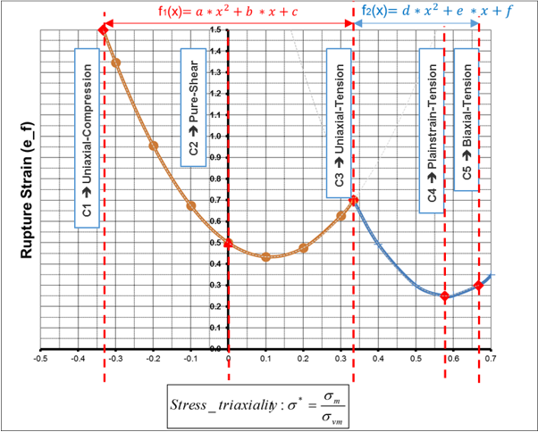
Figure 1.The parameters for the 2 parabolic failure strain curves versus the state of stress (stress triaxiality) are calculated iteratively by Radioss during the initialization phase using the input c1-c5 values. The calculated parabolic failure curve parameters a, b, c, d, e and f, can be reviewed in the starter output file.
If the calculated parabolic failure strain curves have negative failure strain values, these negative values will be replaced by a failure strain of 1E-6 which results in a very high damage accumulation and brittle behavior.
This failure criteria is usable for all elasto-plastic material models with shells and solids.
-
By default, the values different than 0 for c1 to c5 need to be entered. However, specific default behaviors exists, in case failure information are missing.
- In case the material failure behavior is unknown, c1 to c5 are set to 0.0 and the mild steel behavior (M-Flag=1) is used.
- If only the tensile failure value is known, c3 is defined ( ). The mild steel behavior is used and scaled by the user- defined c3 value.
- In case the material behavior is known, M-Flag is defined and c3 can be used to adjust the failure model according the expected tensile failure. The selected material behavior is scaled by the user-defined c3 value.
- For all other cases, all c1 to c5 are intended to be defined and default value of 0.0 is used.
- The plastic strain at failure from physical tests can be input as c1 – c5.
- If failure strain data is not available
then the material flag, M-Flag, can be used to select predefined
failure values for some material.If M-Flag > 0, the entered c1, c2, c4 and c5 values will not be used and instead will be calculated using the predefined ratio values from:If c3 =0 and M-Flag ≠ 0, c3 values will also be used :
M-Flag Roughly Corresponds to Material c3 (Default)
r1 r2 r4 r5 1 Mild steel 0.60 3.5 1.6 0.6 1.5 2 HSS steel 0.50 4.3 1.4 0.6 1.6 3 UHSS steel 0.12 5.2 3.1 0.8 3.5 4 Aluminum AA5182 0.30 5.0 1.0 0.4 0.8 5 Aluminum AA6082-T6 0.17 7.8 3.5 0.6 2.8 6 Plastic PA6GF30 0.10 3.6 0.6 0.5 0.6 7 Plastic PP T40 0.11 10.0 2.7 0.6 0.7 99 Self-defined values (optional line) 0.30 Optional input Optional input Optional input Optional input *Neither Altair nor the authors assume any responsibility for the validity, accuracy or any results obtained from these values. The user must verify his own values by reasonable test results. Usage is only recommended for early design exploration.- If c3 > 0, the selected material behavior is scaled by c3 and the r1 to r5 predefined ratio values.
- If the M-Flag=99, failure strain ratios r1, r2, r4 and r5 must be input in a following additional line.
- Damage is accumulated linearly and can be post-processed in the animation files using the output request /ANIM/SHELL/DAMA/ALL or /ANIM/BRICK/DAMA/111. For shells elements when an integration point reaches , the integration points stress tensor is set to zero. The element fails and is deleted when the percentage of through thickness failed integration points equals P_thickfail. Any P_thickfail value defined in the shell properties are ignored and instead the value entered in this failure model is used. In solid elements, the element is deleted when any integration point reaches .
- If
/PERTURB/FAIL/BIQUAD is used, M-Flag > 0 must be
used and the scatter will be applied to the c3 value only. The
resulting c1, c2, c4, and
c5 values will be calculated using the failure strain ratios thus
applying the perturbation noise to the entire failure strain curve.
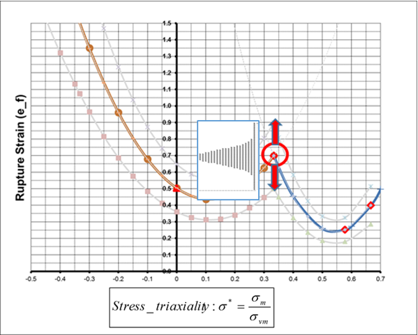
Figure 2. - Special features are activated by this
flag:
S-Flag= 1: failure curves created. 1.
S-Flag= 2: Ensures value c4 as global minimum. To achieve this, the second equation is split into 2 separate quadratic sub-functions where the minimum value of the curves is at c4.
Where, .
S-Flag=3: Same as S-Flag= 2 plus a simplified localized necking criteria. The localized necking criteria is based on the Marciniak-Kuczynski analysis. It uses two additional quadratic functions that define a curve that represents the start of localized necking between stress triaxiality and . The minimum value of this curve is defined by the user in the Inst_start field and occurs at plane strain tension . Using this curve, a second localized necking damage value is calculated and failure only occurs when all integration points reach .
The Inst_start value can be estimated as the (true plastic) strain at maximum stress, from the uniaxial tension test.
- The fail_ID is used with /STATE/BRICK/FAIL and /INIBRI/FAIL and /PERTURB/FAIL/BIQUAD. There is no default value. If the line is blank, no value will be output for failure model variables in the /INIBRI/FAIL (written in .sta file with /STATE/BRICK/FAIL option).