Throttle-off Turn-in
A Throttle-off Turn-in event simulates the dynamics of a vehicle driving a constant radius turn at steady state, the reaction of the vehicle due to a sudden removal of drive torque during the cornering event, and the reaction of the vehicle to a slowly applied ramp steer. The event includes a short straight section to allow the vehicle to come to steady state, the constant radius circle, throttle removal, and the increasing ramp steer. The event is designed to simulate a highway exit ramp maneuver with a decreasing radius turn on the exit ramp. Appropriate vehicle and tire output requests are included. A plot template is available to plot the results.
This event is similar to Throttle-off Cornering.
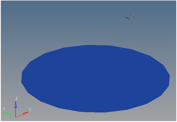
Figure 1. Throttle-off Turn-in event
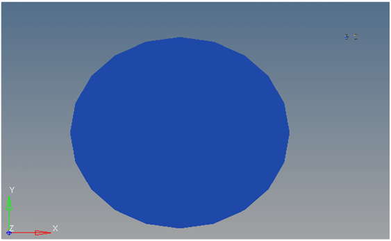
Figure 2. Top View of a Throttle-off Turn-in event
Description
This event is designed to work with a full vehicle model that has been built through the MotionView Assembly Wizard. The event should attach to the model automatically when added through the Task Wizard. It can be used with models built manually, as long as the attachment scheme in the event is strictly followed.
| Input | Units | Description |
|---|---|---|
| Lateral acceleration | Gs | The prescribed lateral acceleration that the vehicle will generate during the constant radius portion of the event. |
| Circle radius | Meters | The radius of the circle that the vehicle CG will follow during the constant radius portion of the event. |
| Turn direction | Left or right | Direction the vehicle turns during the event (as seen by the driver). |
| Vehicle velocity | Miles/hour | Calculated speed that will generate the prescribed Lateral Acceleration at the defined circle radius. Uses the equation: |
| Throttle delay | Sec | The absolute time in the simulation that the throttle controller begins removing drive torque. |
| Throttle duration | Sec | The length of time the throttle controller takes to completely remove the drive torque. |
| Steer delay | Sec | The absolute time in the simulation that the steering angle begins to ramp. |
| Steer ramp rate | Deg/sec | The rate the steering is increased in degrees/sec at the steer delay time. |
| Step size | Sec | The output data step size in seconds (if the number is .02, data is output every .02 seconds). |
| Ground Z coordinate | mm | Calculated location of the ground Z coordinate (do not modify). |
The event sequence is as follows:
- Time
- Description
- 0
- Static analysis - Model is solved for static analysis.
- 0+
- Post Static - Two joints holding the vehicle to ground are released; four motions fixing wheels to spindles are released.
- Varies
- Turn In - Vehicle enters the constant radius corner.
- Per the event input
- Throttle Delay Time - The vehicle drive torque is ramped to zero over the throttle duration time.
- Per the event input
- Steer Delay Time - Steering wheel angle is increased at the steer ramp rate value to simulate a decreasing radius steer event.
- Steer Delay Time +10 seconds
- Event End - The event ends 10 seconds after the steer delay time. The end time can be edited in the event template if a different time is required.
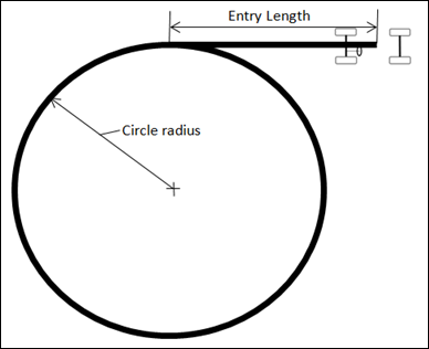
Figure 3. Throttle-off Turn-in
The event is designed to simulate a vehicle exiting a highway using a curved exit ramp with a decreasing radius. The throttle delay time is when the driver takes their foot off the throttle. The steer ramp time is when the decreasing radius begins. You must sequence the event times and the circle radius to match the test conditions or the field conditions being simulated. When simulated with our reference model, the event shows the lateral and fore-aft weight transfer expected in an event such as this.
The lateral acceleration, circle radius, throttle delay and throttle step duration, steer can be modified via the event data form. The turn direction can also be changed to turn left or right. The ground Z coordinate is a calculated value and should not be changed.
A steer controller and a drive torque controller are included in the event. The steer controller provides steering control to the vehicle. The drive torque controller maintains a constant speed using a drivetrain torque during the event, until the throttle delay time, when the torque is ramped off. Both controllers should be tuned to match the characteristics of the vehicle. The controllers are contained in each event and as a result, need to be set for each event.
Nine types of modeling element containers are used to define the event (see below). Three subsystems (Output Requests, a Steer controller, and a Drive torque controller) are also included during the event.
Attachments
The event uses the standard event attachment. The attachments resolve automatically if the model is built through the Model Wizard. The attachments contain the minimum data the event needs to run the analysis. The attachments are standard for most events.Datasets
One dataset is used in the system and it contains the data used to describe the event actions. The event allows you to set the Lateral Acceleration, Circle Radius, Throttle delay, Throttle duration, Steer delay, Steer ramp rate and Step size. The Turn Direction can be set to left or right, depending upon your requirements. The initial Vehicle velocity, wheel rotational velocities and ground height are calculated values and should not be changed manually.Forms
The Form is the only place that you should change the Throttle-off turn-in event. Lateral Acceleration, Circle Radius, Throttle delay, Throttle duration, Steer delay, Steer ramp rate and Step size are the parameters that can be changed. The Turn Direction can be set to left or right, depending upon your requirements. The Ground z Coordinate is a calculated value and is calculated using the left front wheel CG Z location and the tire rolling radius from the Tire Data Form.Graphics
One graphic is defined in the event. The graphics define the road surface graphics and should not require any user input.
Skidpad graphics are included to illustrate the path being driven and are defined parametrically using the data in the Throttle-off turn-in Form. Skidpad graphics should never require editing, unless the event is being fundamentally changed.
Joints
A ball joint is included in the Throttle-off turn-in event. The joint attaches a dummy body to the steering rack. The joint is included to make certain events work in ADAMS. Attach the dummy body to the steering rack if building a model manually.Markers
One marker is included in the Throttle-off turn-in event. The path origin is the origin of skidpad graphics and is parametrically defined to be the CG of the vehicle body. The markers refer to points and the points contain the parametric logic.Motions
Three motions are included in the event. The steering motion is provided by the Steer controller and it acts on a revolute joint that connects the steering wheel to the vehicle body. If a steering column is not included in the model, the joint acts between the steering rack input shaft and the vehicle body.
The Front and Rear Wheel Motions act on the wheel spindle revolute joints that connect the wheel hub to the knuckle. The motion is initially zero (fixing the wheels to the knuckle) so the model converges statically. The motions are deactivated after static analysis to allow the tires to rotate during the dynamic analysis.
Points
Two points are defined in the event. All points are used to create the skidpad graphics. The points contain parametric logic to define their X, Y, and Z locations. You should not need to modify any points.Solver Variables
The Throttle-off turn-in consists of only one solver variable, the Steer Path Variable, which calls a user subroutine to apply an input at the steering wheel in order to follow the desired path.Templates
A template is included in the Throttle-off turn-in event task. The template is solver specific and only the MotionSolve template is documented. The template is inserted in the solver deck after the </Model> command and controls the execution of the event.<ResOutput
angle_type = "YPR"
/>
<ResOutput
mrf_file = "TRUE"
/>
<ResOutput
plt_file = "TRUE"
/>
<H3DOutput
switch_on = "TRUE"
increment = "1"
/>
<ResOutput
abf_file = "TRUE"
/>
{if (tire_dataset.opt_omega.ival ==1)}
<!--Initial static analysis -->
<Simulate
analysis_type = "Static"
end_time = "0.0"
/>
{endif}
<Deactivate
element_type = "MOTION"
element_id = "{mot_frnt_wheel.l.idstring}"
/>
<Deactivate
element_type = "MOTION"
element_id = "{mot_frnt_wheel.r.idstring}"
/>
<Deactivate
element_type = "MOTION"
element_id = "{mot_rear_wheel.l.idstring}"
/>
<Deactivate
element_type = "MOTION"
element_id = "{mot_rear_wheel.r.idstring}"
/>
{if (tire_dataset.opt_omega.ival ==2)}
<!--Initial static analysis -->
<Simulate
analysis_type = "Static"
end_time = "0.0"
/>
{endif}
<Deactivate
element_type = "JPRIM"
element_id = "{j_clamp_1_body.idstring}"
/>
<Deactivate
element_type = "JPRIM"
element_id = "{j_clamp_2_body.idstring}"
/>
<Motion_Joint
id = "{wh_motion.idstring}"
expr = "VARVAL({sv_path.idstring})"
/>
<Simulate
analysis_type = "Transient"
end_time = "{ds.str_dly.value+10}"
num_steps = "{(ds.str_dly.value+10)/ds.step.value}"
/>
<Stop/>References
ISO 9816-2006 Passenger cars — Power-off reaction of a vehicle in a turn.