Braking In a Turn
A Braking in a Turn event simulates a vehicle decelerating in a circular path. The purpose of this event is to measure the stability of a vehicle while braking and turning. The vehicle is driven straight for the entry length and then turns onto the circular path. At the time to apply brakes, the brake torque is ramped on using the brake step duration time so the vehicle slows at the desired deceleration rate. The event ends at the end of simulation time.
Figure 1. Braking in a Turn event
Figure 2. Top View of a Braking in a Turn event
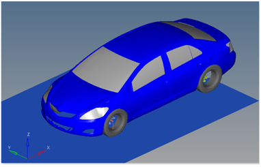
Figure 3. Vehicle Model with Body Graphics
| Time | Description | Details |
|---|---|---|
| 0 | Static Analysis | Static analysis is performed on the vehicle. |
| 0+ | Fixed Joints Released | Two joints holding the vehicle to the ground are released, and the four joints holding the wheels to the knuckle are released. The event template contains the commands that release the joints. |
| Varies | Drive Straight | The vehicle drives straight for the entry length distance. The entry length is ¼ of the circumference of the circle. The speed is calculated using the desired lateral acceleration and the track radius. |
| Varies | Constant Radius Corner | The steer controller turns on to the constant radius circle and the vehicle settles into steady-state cornering. |
| User Defined | Begin Brake Apply | The brakes are applied at the apply brakes time. Braking increases from zero G’s to the desired deceleration, linearly over the brake step duration time. |
| End | Simulation Ends | Enter the simulation end time. |
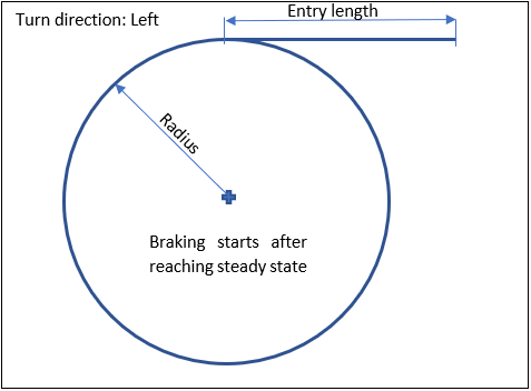
Figure 4. Path for the Braking in a Turn Test
- The vehicle is driven at a constant speed until the braking event begins using the drive torque controller.
- The steer controller steers the vehicle using a motion at the steering wheel or steering gear input shaft and is described here.
- The vehicle velocity is calculated using the lateral acceleration, the circle radius and the equation v=sqrt(radius*acceleration). A number of unit conversion factors are required to convert to the model units of millimeters and seconds.
- The brake torque controller maintains the desired deceleration.
- You are responsible for entering the braking and event end times that are consistent with the path and the time required for the vehicle to respond to the various inputs.
Nine types of modeling element containers are used to define the event. Four sub-systems (output requests, steer controller, drive torque controller, and brake torque controller) are also included in the event.
Datasets
One dataset is used in the system and it contains the data used to describe the Braking in a Turn event. The event allows you to set the lateral acceleration, circle radius, turn direction (left or right), end of simulation time, time to apply brakes, desired deceleration and brake step duration. The initial velocity, wheel rotational velocities and ground height are calculated values and should not be changed.
Forms
The form is the only place that you should change the lane change event. lateral acceleration, circle radius, time to apply brakes, end of simulation time, desired deceleration and brake step duration are the parameters that can be changed. The turn direction can be either left or right, and it is user-dependent. The ground z coordinate is a calculated value and is calculated using the wheel CG Z location and the tire rolling radius from the tire data form.
Graphics
One graphic is defined in the event. The graphics define the road surface graphics and should not require any user input. A full description of the graphics can be found here.
Skidpad graphics are included to illustrate the path being driven, and are defined parametrically using the data in the Braking in a Turn event form. Skidpad graphics should never require editing unless the event is being fundamentally changed.
Joints
A ball joint is included in the Braking in a Turn event. The joint attaches a dummy body to the steering rack. The joint is included to make certain events work in ADAMS. Attach the dummy body to the steering rack if building a model manually.
Markers
One marker is included in the Braking in a Turn event. The path origin is the origin of skidpad graphics and is parametrically defined to be the CG of the vehicle body. The markers refer to points and the points contain the parametric logic.
Motions
Three motions are included in the event. The steering motion is provided by the steer controller to steer the vehicle, and it acts on a revolute joint that connects the steering wheel to the vehicle body. If a steering column is not included in the model, the joint acts between the steering rack input shaft and the vehicle body.
The front and rear wheel motions act on the wheel spindle revolute joints that connect the wheel hub to the knuckle. The motion is initially zero (fixing the wheels to the knuckle) so the model converges statically. The motions are deactivated after the initial static analysis to allow the tires to rotate during the dynamic analysis.
Points
Two points are defined in the event. All points are used to create the skidpad graphics. The points contain parametric logic to define their X, Y, and Z locations. You should not modify any points.
Solver Variables
The Braking in a Turn event consists of only one solver variable, the Steer Path variable, which calls a user subroutine to apply an input at the steering wheel in order to follow a desired path.
- Number
- Description
- 5020
- Branching ID. 5020 is a Braking in a Turn event.
- 70000000
- The ID of a solver array containing Driver Model Controller data. The array is in the steer controller system.
- 70000100
- The ID of a Vehicle Data array containing vehicle information. The array is in the steer controller system.
- 30
- The value of the circle radius.
Templates
The template is solver specific, and only the MotionSolve template is documented. The template is inserted in the solver deck after the </Model> command and controls the execution of the event.
<ResOutput
     angle_type          = "YPR"
  />
  <ResOutput
     mrf_file            = "TRUE"
  />
  <ResOutput
     plt_file            = "TRUE"
  />
  <H3DOutput
     switch_on           = "TRUE"
     increment           = "1"
  />
  <ResOutput
     abf_file            = "TRUE"
  />
{if (tire_dataset.opt_omega.ival ==1)}
<!--Initial static analysis -->

<Simulate
	analysis_type = "Static"
	end_time      = "0.0"
/>
{endif}

 <Deactivate
	element_type = "MOTION"
	element_id = "{mot_frnt_wheel.l.idstring}"
/>
<Deactivate
	element_type = "MOTION"
	element_id = "{mot_frnt_wheel.r.idstring}"
/>
<Deactivate
	element_type = "MOTION"
	element_id = "{mot_rear_wheel.l.idstring}"
/>
<Deactivate
	element_type = "MOTION"
	element_id = "{mot_rear_wheel.r.idstring}"
/>
{if (tire_dataset.opt_omega.ival ==2)}
<!--Initial static analysis -->

<Simulate
	analysis_type = "Static"
	end_time      = "0.0"
/>
{endif}
<Deactivate
	element_type = "JPRIM"
	element_id = "{j_clamp_1_body.idstring}"
/>
<Deactivate
	element_type = "JPRIM"
	element_id = "{j_clamp_2_body.idstring}"
/>

<Motion_Joint
     id                  = "{wh_motion.idstring}"
     expr                = "VARVAL({sv_str_path.idstring})"
/>
<Simulate
	analysis_type = "Transient"
	end_time      = "{ds.end_of_sim.value}"
	num_steps     = "{ds.end_of_sim.value*50}"
/>

<Stop/>
References
ISO 7376-2006 - Passenger cars - Braking in A Turn - Open-loop test method.