The Suspension Design Process
A widely used process in the automotive industry is to split the suspension design and development into three distinct stages. The stages are typically performed by different teams working in different locations and at different times during the vehicle program. Ideally, the teams will share model data, modeling methods, and results widely. Since the teams are working on the same vehicle, the engineering lessons learned by one group will need to be shared with the other two teams.
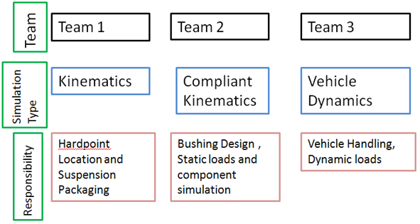
Figure 1.
Team 1 - Kinematics
The Kinematics team is responsible for the overall vehicle packaging. They design the suspension to have good geometry characteristics, meet packaging requirements, create appropriate clearance between components during suspension travel, and meet load and stiffness requirements for the suspension and chassis.
The geometry characteristics of the suspension are typically defined by the caster, camber and toe curves, the Ackerman error during steering, and the suspension design factor calculations.
MotionSolve calculates metrics for the suspension which we call Suspension Design Factors (SDFs). These are also referred to as Static Design Factors or Suspension Design Parameters in the engineering community. These metrics are stored in tabular format in the .sdf file and can be plotted via the .abf or the .plt file in HyperView.
MotionSolve's Assembly Wizard allows most suspensions to be built as kinematic mechanisms. The resulting model can be populated with the correct geometry points and used to simulate the suspension. Simulation events can be added using the Task Wizard and will perform ride, roll, and steer events on the suspension geometry. The SDFs are built into the model and are calculated for all of the events. Report templates are available for all of the events which create a series of plots for each event, with standard factors plotted for each event.
Interference and proximity checking is performed in HyperView. CAD geometry of the suspension components and chassis can be imported into HyperView and used to measure clearance and identify contact between components during suspension motion.
The Kinematics team is able to perform their packaging and suspension geometry development using the vehicle hard-point locations. Complete bushing and tire data is not required at this phase of the design. This process allows the group to design and package the suspension and postpone the exact design of the tire and bushing characteristics to a later phase.
Team 2 - Compliant Kinematics and Loads
The Compliant Kinematics team is responsible for the characteristics of the rubber components in the suspension. They work with the NVH team to develop the suspension bushings, springs and stabilizer bars so they meet the program requirements. The bushing rates, in combination with the suspension geometry, control the deflection characteristics of the suspension, which represents the “feel” of the suspension to the driver.
The team typically uses a Kinematics and Compliance Measurement machine to measure the characteristics of the suspension. The Kinematics and Compliance Measurement (K&C) machine is designed to test a full vehicle, but only measure the characteristics of the suspension, so the suspension can be designed independently of the tire.
The MDL vehicle library supports this design phase by building half-car models of suspensions, with bushings and stabilizer bars to simulate the compliant properties of the suspension. Rigid bodies can be made into a flexible body using a finite element model to understand the structural contribution of the suspension component to the suspension performance.
All of the standard SDF output is included in the model as standard requests. Ride, roll, and steering events can be included in the model as standard predefined events. A Kinematics and Compliance event is included, which mimics all of the standard individual tests performed by a K&C machine. The K&C event exercises the suspension in all directions, and an available report template will generate a series of plots that plot the typical K&C metrics.
This team also generates suspension loads. The “G” loading methodology is used to calculate input loads at the wheel center or tire patch, typically for all three directions of force input (vertical, lateral, and longitudinal). The resulting loads can be used for FEA analysis of the suspension components and the chassis or body. Free body diagrams of the loads can be generated in HyperView.
Team 3 - Vehicle Dynamics
The Vehicle Dynamics team is typically responsible for developing a safe and stable vehicle which feels good to the driver. The team is typically responsible for the tires and also has significant input into other suspension design characteristics, such as bushing, spring and stabilizer rates. The vehicle must handle properly at both the curb weight and fully laden. Many vehicles also are required to pull trailers. The wide variety of vehicle operating conditions can make the dynamics' problem challenging.
The MDL vehicle library supports this phase by building and analyzing a complete vehicle model, including the front and rear suspensions, powertrain and drivetrain, steering system (including the column), and a tire model. Tire models are empirical and can be a simple Fiala model (vertical force plus a lateral force-slip angle), a handling model (Pacejka-style coefficients), or a durability model such as Ftire. Models such as CDtire and RMODK can be supported with some minor modifications to the MDL. Tire data requests are included in the vehicle model so that all of the tire information (six state variables and six forces and moments) are available in either an SAE or an ISO reference frame.
There are a wide variety of full vehicle events in the library. Most standard lateral transient vehicle characterization tests can be simulated using the predefined events. Steep steer, constant radius, lane change, steady-state acceleration and deceleration are all included in the library. Standard post-processing reports are also included that plot vehicle response and tire information.
The vehicle model is one of the most challenging to populate. A wide variety of data is required which comes from different sources, and may be in different units. Inertia data of the complete vehicle needs to be accurate to get good lateral response correlation. The tire data needs to be accurately described at the slip angle and vertical loads that are simulated in the events. Historical data can be used early in a program when the product is being developed and improved. Almost all data needs to be measured and verified to correlate well to a full vehicle test.