Static Ride Analysis
The Static Ride analysis is a simulation of both wheels moving up and down, in phase, with the steering wheel held fixed. The chassis is fixed-to-ground. The displacement of the wheel center is prescribed by the user. The suspension moves via a simple control system and a “suspension test rig”. The wheel is constrained at the tire patch location to the suspension test rig using an in-plane joint. Standard suspension requests (caster, camber, toe, etc.) are included as part of the ride analysis and are described here. The front and rear suspension ride analyses are similar.
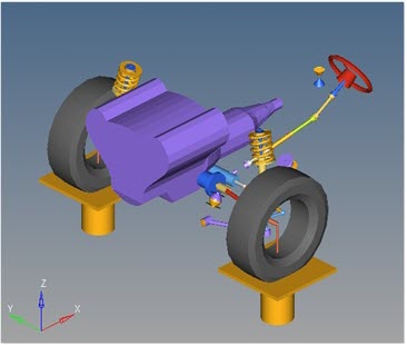
Figure 1. Front Suspension Static Ride Analysis
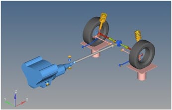
Figure 2. Rear Suspension Static Ride Analysis
- Time (in seconds)
- Action
- 0 to 2.5
- Wheels move from design position to jounce position
- 2.5 to 5.0
- Wheels move from jounce position to design position
- 5.0 to 7.5
- Wheels move from design position to rebound position
- 7.5 to 10.0
- Wheels move from rebound position to design position
- 10.0
- Analysis ends.
Suspension travel is entered on the Static Ride Parameters form in the analysis. Travel is assumed to be symmetric. The suspension displacement follows a simple harmonic function (sin wave) pattern.
A total of forty-seven outputs are calculated, including all of the Suspension Design Factors. Input data for the SDFs are entered on the Vehicle Parameters form in the Static Ride analysis.
How the Analysis Works
- A Jack body is included in the analysis.
- The Jack body is constrained to ground with a translational joint, allowing the Jack body to only move in the vertical direction.
- An Inplane joint constrains the jack to the wheel at the SLR distance entered in the Vehicle Parameters form.
- The solver variables Left Command Variable and Right Command Variable define the desired displacement of the Jack bodies.
- The solver variables Left Feedback Variable and Right Feedback Variable measure the distance in the Z direction between the wheel center point on the wheel, and the wheel center point on the ground.
- Solver differential equations diff left jack and diff right jack are defined as the difference between the Feedback and Command variables. An IF statement and the MODE function is used to turn the solver differential equation on during statics and quasi-statics and set it to zero (turning off the solver differential equation) during the remaining analysis modes (Kinematics, Initial Conditions, Dynamics, and Linear Analysis).
- A force Jack vertical actuator is defined to be the DIF (value) of the
solver differential equation diff left jack using an
expression.
The Jack vertical actuator force moves the suspension through jounce and rebound. The force magnitude is determined by the differential controller value.
- The control system and test rig mechanism does not add constraints to the suspension. This allows the wheel center compliance matrix to be calculated easily, which is used in the suspension design factor calculations.
- A force is applied on the test rig “Jack” to move the wheel center vertical (Z) displacement through a prescribed motion. A control system is required for this type of system