Single Lane Change

The Single Lane Change event drives the vehicle through a single lane change, attempting to follow the centerline of the defined lane. You can define the speed of the lane change, along with the lane dimensions. A steering controller is used to follow the path and a torque controller is used to maintain speed through the event. The event supports right and left lane changes. A plot template is available to plot the results.

A Single Lane Change event does not have specific metrics associated with it. A lane change is typically used as a subjective evaluation test, but it is difficult to create objective metrics of the test.
Note: A Double Lane Change test is also available.


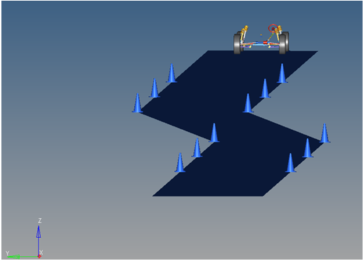
Figure 1. Single Lane Change Event


Figure 2. Top View of a Single Lane Change Path


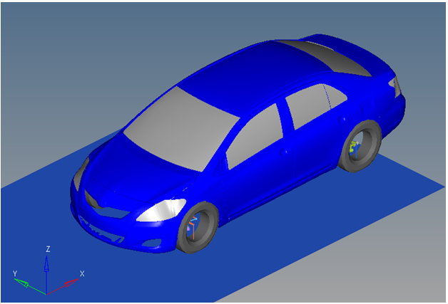
Figure 3. Vehicle Model with Body Graphics

The event is comprised of an initial straight section of road, a transition section, and a recovery straight section. In the initial straight section, the vehicle settles into a steady state condition. The transition section is the actual lane change. The vehicle recovers in the final straight section and terminates the simulation. The vehicle maintains a constant velocity (via the torque controller) in the event. The vehicle steering controller is designed to keep the CG of the body on a path at the centerline of the road.

The initial speed, longitudinal and lateral spacing of the cones, and lane graphics can be modified via the event form . The ground Z coordinate is a calculated value (the blue background designates a calculated value) and is calculated by subtracting the front left tire rolling radius from the front left tire CG Z location.

A test model runs this simulation in 60 seconds. Approximately 0.5G lateral is developed by the test vehicle model and default lane change parameters. Increasing the speed and lateral spacing of the cones increases the lateral G forces developed by the vehicle. As the vehicle approaches its limits of handling, the model will yaw excessively or will not complete the lane change. The error Could not Find Ideal SWA in 20 Iterations may be displayed in the log file, indicating that the steering controller is unable to follow the defined path.

The Single Lane Change event is parametrically defined per the diagram below.


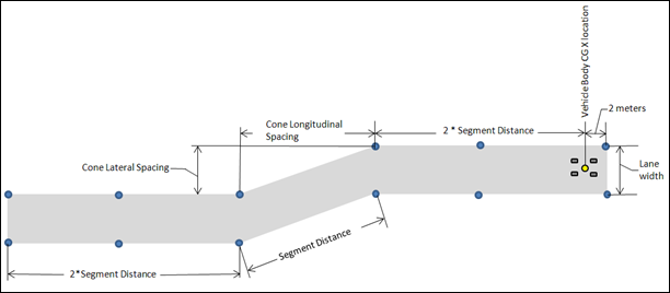
Figure 4. Single Lane Change Event - Road Graphics Parametric Definition

The cone spacing (laterally and longitudinally) and the lane width can be changed, along with the vehicle speed. Use the event form to change these parameters.

Attachments

The event attaches to the model as shown in the picture below. All of the attachments need to be resolved to write out the model. The attachments are the references in the model required for the event to run.


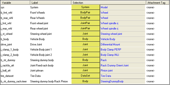
Figure 5. Single Lane Change Event - Attachments
Variable Label Description
sys System The master system, in this case “Model”.
b_frnt_whl mot_frnt_wheel Front wheel body pair.
b_rear_whl mot_rear_wheel Rear wheel body pair.
J_frnt_whl Front Wheel Joint Revolute joint connecting the front wheels to the knuckle.
J_rear_whl Rear Wheel Joint Revolute joint connecting the rear wheels to the knuckle.
J_st_wheel Steering Wheel Joint Revolute joint connecting the steering wheel to the body or the steering gear input shaft to the body, if a steering column is not included.
B_body Vehicle Body The vehicle body.
Drive_joint Drive Joint The joint used to drive the vehicle, which varies depending on the drivetrain. It is typically the revolute joint in the drivetrain closest to the engine.
J_clamp_1_body Vehicle Body Joint 1 Vehicle body clamp one. One of two clamps used to hold the vehicle fixed during static simulation.
J_clamp_2_body Vehicle Body Joint 2 Vehicle body clamp two. The second clamp used to hold the vehicle fixed during static simulation.
b_str_dummy Steering Dummy Body The Rack in a rack and pinion steering system. The relay rod in a Parallelogram steering system.
J_rackfix_att Joint Fixed Rack-Body Rack dummy orient joint in a rack and pinion steering system. Idler Arm ball in a parallelogram system.
J_ball_att Joint Pitman The pinion joint in a rack and pinion steering system. The pitman arm ball joint in a Parallelogram system
Tire_dataset Tire Data Dataset containing the tire information from the tire system.
b_str_dummy_racksteer Steering Dummy Body Rack Pinion Steering dummy body in both parallelogram and rack and pinion steering systems.

References

ISO 3888-2-2011 Passenger cars — Test track for a severe lane-change maneuver.

NATO Allied Vehicle Testing Publication AVTP: 03-160 Sep. 1991.

Creating a Single Lane Change Event

  1. Click the Task Wizard and select the Single lane change analysis option.
  2. Click Next.
  3. Click Finish.
    The Project Browser populates with the new data, and the Car/Small truck - Full vehicle tasks dialog opens.
  4. Review the data in the dialog and click Next.
    Car/Small truck - Full vehicle tasks dialog displays the steer controller data.
  5. Review the data and click Next.
    Car/Small truck - Full vehicle tasks dialog displays the drive torque controller data.
  6. Click Finish.
  7. In the Project Browser, under Single lane change analysis, expand Data Sets and click on Full Vehicle Data.
    The dataset contains the data used to describe the lane change. The four parameters at the top of the dataset, shown with a white background, can be changed to modify the event using the Single Lane Change form. The six parameters at the bottom of the dataset are calculated parameters and should not be changed. The blue background signifies a calculated parameter. The dataset should not require any user input.
    Figure 6.
  8. In the Project Browser, expand Forms and click on Single lane change data.
    The form is the only place that you should change the lane change event. Vehicle velocity and the lane change geometry are the parameters that can be changed. All lane change data and vehicle path graphics are defined parametrically using these four inputs. The ground Z coordinate is a calculated value (designated by a blue background) and is calculated using the left front wheel CG Z location and the tire rolling radius from the tire data form.
  9. In the Project Browser, expand Graphics.
    The road graphics are included to illustrate the path being driven and are defined parametrically using the data in the single lane change form. All road graphics are used to illustrate the lane dimensions, but they are not of the actual road used for calculating tire forces. Road graphics should never require editing unless the event is being fundamentally changed.
    The road used to calculate the tire forces is at the same height as the road graphics and is defined by the road file (.rdf) in the tire system. The default flat road file in the vehicle library is an infinitely large flat road with a coefficient of friction of 1.0. The road file is an ASCII file that can be edited.


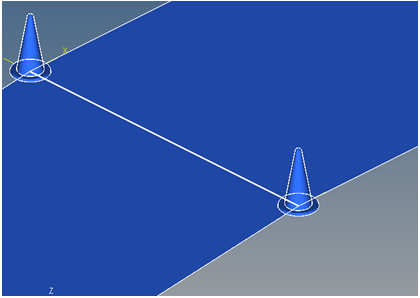
    Figure 7. Cone Graphics


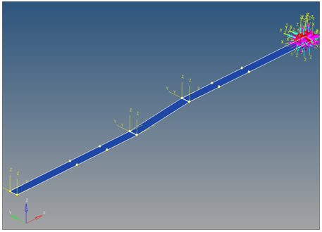
    Figure 8. Road Graphics
  10. In the Project Browser, expand Joints and click on Rack Dummy Ball.
    A ball joint is included in the Single lane change event. The joint attaches a dummy body to the steering rack. The joint is included to make certain events work in ADAMS. Attach the dummy body to the steering rack if building a model manually.
  11. If building a model manually, attach the dummy body to the steering rack using the panel.
  12. In the Project Browser, expand Markers.
    Nine markers are included in the Single Lane Change event. The markers are used to define the lane graphics (cones and the lane road surface).

    The path outline markers point to the path outline points for their XYZ location. The points are parametrically defined using the event input data. Path origin is the origin of all lane change graphics and is parametrically defined to be the CG of the vehicle body.

    None of the markers should require any user input.

  13. In the Project Browser, expand Motions.
    Three motions are included in the event. The steering motion to the vehicle is provided by the steering controller and acts on a revolute joint that connects the steering column to the vehicle body. If a steering column is not included in the model, the joint acts between the steering rack input shaft and the vehicle body.
    Steering Wheel Motion

    Applies a rotation motion at the steering wheel joint. The motion is initially set to the linear type of value 0 but is modified through the event template to an expression.

    Front Wheel Motion
    Applied at the front wheel spindle and is of type linear and value 0.
    Rear Wheel Motion
    Applied at the rear wheel spindle and is of type linear and value 0.

    The front and rear wheel motions act on the wheel spindle revolute joints that connect the wheel hub to the knuckle. The motion is initially zero (fixing the wheels to the knuckle) so the model converges statically. The motions are deactivated after the static equilibrium analysis to allow the tires to rotate during the dynamic analysis.

  14. In the Project Browser, expand Points.
    Seventeen points are defined in the event. All points are used to create the lane graphics and cones graphics used to illustrate the lanes. The points contain parametric logic to define their X, Y, and Z locations. You should not need to modify any points.
    Path Origin
    Point that locates the origin of the path from where the vehicle starts. This is parametrically set to the vehicle body CG location.
    Path Outline1
    Point used for path graphics; defined parametrically using a variety of data from the model.
    Path Outline2-N
    Additional points used for path graphics; defined parametrically in a similar scheme to Path Outline 1.
    Cone1
    Point used to define the cone graphics; defined parametrically to sit at the edge of the road surface along the path to illustrate the road.
    Cone2-N
    Additional points used to define the cone graphics; defined parametrically to sit at the edge of the road surface along the path to illustrate the road.
  15. In the Project Browser, expand Solver Variables.
    There is one solver variable in the Single Lane Change event. The steer path variable is a user-written subroutine call which returns the steering wheel angle that should be applied to follow the desired path. The motion of the steering wheel is set to this variable in the lane change template. You should not need to edit any portion of the steer path variable.
    The numbers in the solver variable USER subroutine call are as follows:
    5010
    The Branching ID. 5010 is a Single lane change event.
    70000000
    The ID of a solver array containing driver model controller data. The array is in the steer controller system.
    70000100
    The ID of a vehicle data array containing vehicle information. The array is in the steer controller system.
    30.5
    The lane change transition section length in meters.
    3.66
    The lane change width in meters.
  16. In the Project Browser, expand Templates and click on Single Lane Change event.
    The template is solver specific and only the MotionSolve template is documented. The template is inserted in the solver deck after the </Model> command and controls the execution of the event.

    The if (tire_dataset.opt_omega.ival) logic is included to handle legacy models which used the omega method of tire rotation. This method is obsolete and the value will always be equal to 1. The logic will be removed in a future release.

    The first four deactivate commands deactivate the motion between the wheels and the knuckle, allowing them to rotate. The last two deactivate commands turn off the body clamps. Body clamps hold the body rigid during static analysis.

    The Motion_Joint command reassigns the value of the steering wheel joint from zero to the value calculated by the steering controller, essentially turning on the steering controller.

    The Simulate transient command starts the transient simulation and establishes the output time step and end time of the simulation. The data can be edited to change the event. Additional XML commands can be added to enhance the solution. The commands are described in Command Statements section of the MotionSolve Reference Guide.

    The template for this event is shown below. The template has commands for the output files that are generated, the sequence of events that are run, and the run time commands for the forces, joints and motions used to create the pulse steer event sequence.
    <ResOutput
         angle_type          = "YPR"
      />
      <ResOutput
         mrf_file            = "TRUE"
      />
      <ResOutput
         plt_file            = "TRUE"
      />
      <H3DOutput
         switch_on           = "TRUE"
         increment           = "1"
      />
      <ResOutput
         abf_file            = "TRUE"
      />
      
    {if (tire_dataset.opt_omega.ival ==1)}
    <!--Initial static analysis -->
    
    <Simulate
    	analysis_type = "Static"
    	end_time      = "0.0"
    />	
    {endif}
    <Deactivate
    	element_type = "MOTION"
    	element_id = "{mot_frnt_wheel.l.idstring}"
    />
    <Deactivate
    	element_type = "MOTION"
    	element_id = "{mot_frnt_wheel.r.idstring}"
    />
    <Deactivate
    	element_type = "MOTION"
    	element_id = "{mot_rear_wheel.l.idstring}"
    />
    <Deactivate
    	element_type = "MOTION"
    	element_id = "{mot_rear_wheel.r.idstring}"
    />
    {if (tire_dataset.opt_omega.ival ==2)}
    <!--Initial static analysis -->
    
    <Simulate
    	analysis_type = "Static"
    	end_time      = "0.0"
    />	
    {endif}
    <Deactivate
    	element_type = "JPRIM"
    	element_id = "{j_clamp_1_body.idstring}"
    />
    <Deactivate
    	element_type = "JPRIM"
    	element_id = "{j_clamp_2_body.idstring}"
    />
    <Motion_Joint
         id                  = "{wh_motion.idstring}"
         expr                = "VARVAL({sv_path.idstring})"
      />
    <Simulate
         analysis_type       = "Transient"
         end_time            = "6"
         print_interval      = "0.05"
      />
    <Stop/>