Double Lane Change
A Double Lane Change event drives the vehicle through a lane change and a return to lane maneuver, attempting to follow the centerline of the defined lane. You can define the speed of the lane change, along with the lane dimensions. A steer controller is used to follow the path and a drive torque controller is used to maintain speed throughout the event. The event supports right and left lane changes. A plot template is available to plot the results.
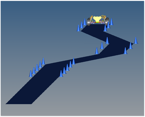
Figure 1. Double Lane Change Event
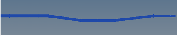
Figure 2. Top View of a Double Lane Change Path
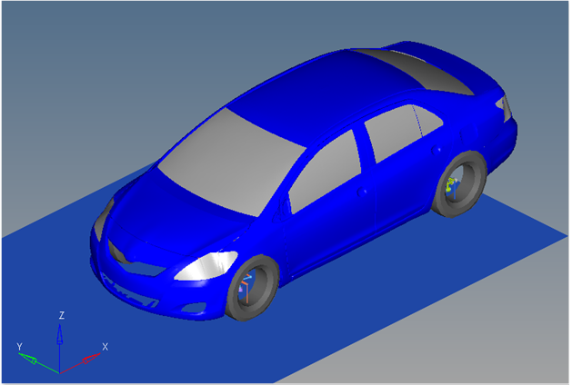
Figure 3. Vehicle Model with Body Graphics
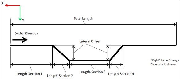
Figure 4. Double Lane Change Path Diagram
The Double Lane Change event path is shown in the diagram above. Lane dimensions are entered in meters and are translated to millimeters in the various locations they are used (point parametric definitions, solver arrays, and so on). The lane graphics are defined from the path dimensions and are used to illustrate the path. The road surface used by the tire is defined by the .rdf file in the tire system and is independent from the graphics.
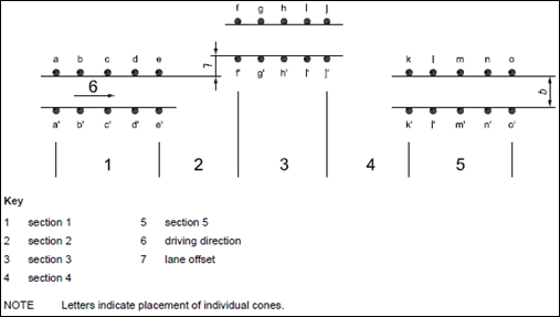
Figure 5. ISO Double Lane Change Diagram (from ISO 3888-2 Part 2 Obstacle Avoidance)
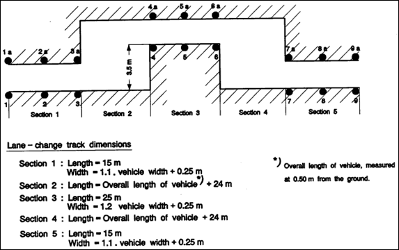
Figure 6. NATO Double Lane Change AVTP 03-160
The initial speed can be modified via the event form. The ground z coordinate is a calculated value (the blue background designates a calculated value) and is calculated by subtracting the front left tire rolling radius from the front left tire CG Z location.
The entities in the event are displayed in the Project Browser.
Nine types of modeling element containers are used to define the event. Two sub-systems (a steer controller and a drive torque controller) are included in the event.
Curves
A single curve is included in the event. The curve is a user written CURSUB that defines the centerline of the path. Path dimensions entered in the Full Vehicle Data dataset are used to define the Lane Parameters solver array. The ID of the solver array is passed to the CURSUB subroutine which generates the curve geometry.
Datasets
One dataset is used in the system and it contains the data used to describe the Double Lane Change event. The event allows you to set the vehicle control, the lane change dimensions, and a Cone - Base diameter. The wheel rotational velocities, ground height, and final section length are calculated values and should not be changed.
Forms
The form contains data to change the event inputs. Vehicle velocity is the only parameter (shown with a white background) that can be changed. The ground z coordinate is a calculated value (designated by a blue background) and is calculated using the left front wheel CG Z location and the tire rolling radius from the tire data form.
Lane dimensions are not included on the form and are changed in the dataset. The Double Lane Change event is setup differently from most events. Future versions of the event will include the lane data on the form.
Graphics
Twenty seven graphics are defined in the event. The graphics define the cones and the road surface graphics and should not require any user input. A full description of the graphics can be found here.
The road graphics are included to illustrate the path being driven and are defined parametrically using the data in the Double Lane Change event form. All road graphics are used to illustrate the lane dimensions, but are not of the actual road used for calculating tire forces. Road graphics should never require editing unless the event is being fundamentally changed.
The road used to calculate the tire forces is at the same height as the road graphics and is defined by the road file (.rdf) in the tire system. The default flat road file in the vehicle library is an infinitely large flat road with a coefficient of friction value of 1.0. The road file is an ASCII file that can be edited.
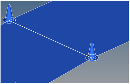
Figure 7. Cone Graphics
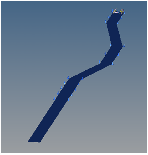
Figure 8. Road Graphics
Joints
A ball joint is included in the Double Lane Change event. The joint attaches a dummy body to the steering rack. The joint is included to make certain events work in ADAMS. Attach the dummy body to the steering rack if building a model manually.
Markers
Thirteen markers are included in the Double Lane Change event. The path origin is the origin of all lane change graphics and is parametrically defined to be the CG of the vehicle body. The markers refer to points and the points contain the parametric logic.
The path outline markers point to the path outline points for their XYZ location. The markers are used to define the lane graphics. None of the markers should require any user input.
Motions
Three motions are included in the event. The steering motion to the vehicle is provided by the steering controller and acts on a revolute joint that connects the steering column to the vehicle body. If a steering column is not included in the model, the joint acts between the steering rack input shaft and the vehicle body on a rack and pinion steering system.
The front and rear wheel motions act on the wheel spindle revolute joints that connect the wheel hub to the knuckle. The motion is initially zero (fixing the wheels to the knuckle) so the model converges statically. The motions are deactivated after the static equilibrium analysis to allow the tires to rotate.
Points
Thirty five points are defined in the event. Points are used to create the lane graphics and graphics for the cones used to illustrate the lanes. The points contain parametric logic to define their X, Y, and Z locations. You should not need to modify any points.
Solver Arrays
The Double Lane Change event contains a solver array called Lane Parameters that defines the path that the vehicle has to travel.
| Parameter Number | Value | Description |
|---|---|---|
| 0 | 1 | Lane type (1=Double lane change). |
| 1 | 1 | Interpolation type (1=Cubic). |
| 2 | 0 | First lane change direction (Left=0, Right =1). |
| 3 | 125000 | Total length (mm). |
| 4 | 15000 | Distance to start of lane change (mm). |
| 5 | 30000 | First Lane Change: Longitudinal distance (mm). |
| 6 | 3500 | First Lane Change: Lateral distance (mm). |
| 7 | 25000 | Distance from end of the first lane change to the start of the second lane change (mm). |
| 8 | 25000 | Second lane change: Longitudinal distance (mm). |
| 9 | 3500 | Second lane change: Lateral distance (in opposite direction to first lane) (mm). |
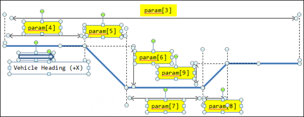
Figure 9. Diagram of Double Lane Change Event
The data point values in the solver array are obtained from the Full Vehicle Data dataset.
Lane data is converted from meters to millimeters in the Data Point panel. The data is
passed to the CURSUB subroutine using the idstring of this array.
Solver Variables
The Double Lane Change event consists of only one solver variable, the Steer Path variable, which calls a user subroutine to apply an input at the steering wheel in order to follow a desired path.
- Number
- Description
- 5000
- The Branching ID. 5000 is a Double Lane Change event.
- 70000000
- The ID of a solver array containing driver model controller data. The array is in the steer controller system.
- 70000100
- The ID of a Vehicle Data array containing vehicle information. The array is in the steer controller system.
- 317001
- The ID of the curve used to define the lane path.
- 1
- The scaling factor for the curve.
Templates
A template is included in the Double Lane Change event task. The template is solver specific and only the MotionSolve template is documented. The template is inserted in the solver deck after the </Model> command and controls the execution of the event. The first four commands define different output datasets. More information about these commands can be found in the MotionSolve Reference Guide.
The if (tire_dataset.opt_omega.ival) logic is included to handle legacy
models which used the omega method of tire rotation. This method is obsolete and the value
will always be equal to 1. The logic will be removed in a future release.
The first four deactivate commands deactivate the motion between the wheels and the knuckle, allowing them to rotate. The final two deactivate commands turn off the body clamps. Body clamps hold the body rigid during static analysis.
The Motion_Joint command reassigns the value of the steering wheel joint from zero to the value calculated by the steering controller, essentially turning on the steer controller.
The Simulate transient command starts the transient simulation and establishes the output timestep and end time of the simulation. The data can be edited to change the event. Additional XML commands can be added to enhance the solution. The commands are described in Command Statements section of the MotionSolve Reference Guide.
<ResOutput
     angle_type          = "YPR"
  />
  <ResOutput
     mrf_file            = "TRUE"
  />
  <ResOutput
     plt_file            = "TRUE"
  />
  <H3DOutput
     switch_on           = "TRUE"
     increment           = "1"
  />
  <ResOutput
     abf_file            = "TRUE"
  />

{if (tire_dataset.opt_omega.ival ==1)}
<!--Initial static analysis -->

<Simulate
	analysis_type = "Static"
	end_time      = "0.0"
/>
{endif}

<Deactivate
	element_type = "MOTION"
	element_id   = "{mot_frnt_wheel.l.idstring}"
/>
<Deactivate
	element_type = "MOTION"
	element_id   = "{mot_frnt_wheel.r.idstring}"
/>
<Deactivate
	element_type = "MOTION"
	element_id   = "{mot_rear_wheel.l.idstring},"
/>
<Deactivate
	element_type = "MOTION"
	element_id   = "{mot_rear_wheel.r.idstring}"
/>
{if (tire_dataset.opt_omega.ival ==2)}
<!--Initial static analysis -->

<Simulate
	analysis_type = "Static"
	end_time      = "0.0"
/>
{endif}
<Deactivate
	element_type = "JPRIM"
	element_id   = "{j_clamp_1_body.idstring}"
/>
<Deactivate
	element_type = "JPRIM"
	element_id   = "{j_clamp_2_body.idstring}"
/>

<Motion_Joint
     id                  = "{wh_motion.idstring}"
     expr                = "VARVAL({sv_path.idstring})"
  />

<Simulate
	analysis_type  = "Transient"
	end_time       = "{350000.0/(ds.veh_vel.value*447.04)}"
	print_interval = "0.02"
/>

<Stop/>
References
ISO 3888-2-2011 Passenger cars — Test track for a severe lane-change maneuver.
NATO Allied Vehicle Testing Publication AVTP: 03-160 Sep. 1991.