Straight Line Braking
A Straight Line Braking event simulates a vehicle slowing in a straight line. The steering wheel is normally held fixed but can be released. A braking torque controller applies torque at the wheels to slow the vehicle and appropriate output requests are included. A plot template is available to the plot the results.
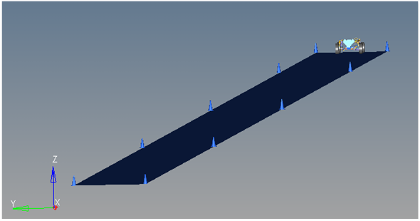
Figure 1. Straight Line Braking event
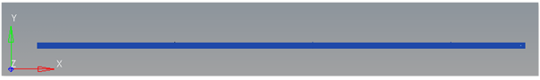
Figure 2. Top View of a Straight Line Braking event

Figure 3. Vehicle Model with Body Graphics
Description
The Straight Line Braking event is designed to work with a full vehicle model that has been built through the MotionView Assembly Wizard. The event should attach to the model automatically when added through the Task Wizard. The event can be used with models built manually, as long as the attachment scheme in the event is strictly followed.
- Time
- Description
- 0-1 second
- Vehicle settles into steady state at the initial velocity entered on the event Form (default is 50 mph).
- 1-2 seconds
- Transition from steady state to the prescribed deceleration rate.
- 2-4 seconds
- Vehicle is at steady state deceleration.
The initial speed and the desired acceleration can be modified via the event form. You can also change the steering condition, which can be locked or free.
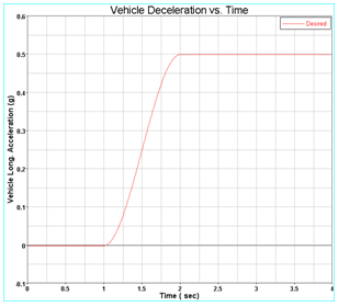
Figure 4. Vehicle Deceleration vs. Time
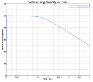
Figure 5. Vehicle Speed vs. Time in the Straight Line Braking Event
Attachments
The event uses the standard event attachment. The attachments resolve automatically if the model is built through the Model Wizard. The attachments contain the minimum data the event needs to run the analysis. The attachments are standard for most events.Curves
A single curve is included in the event. The curve is not used by the event but is included in case you want to switch to an event that is driven on a straight line. The steering controller needs to be added manually in order to perform a straight line drive.Datasets
One dataset is used in the system, which contains the data used to describe the Straight line braking event. The event allows you to set the initial Vehicle velocity, Lane Width, desired acceleration and steering state (locked or free). Modify the dataset values using the Form. The wheel rotational velocities and Ground z Coordinate are calculated values and should not be changed.Forms
The Form is the only place that you should change the Straight line braking event. Vehicle velocity, desired acceleration and steering condition are the parameters that can be changed. The steering condition can either be locked or free, depending upon the user requirement.Graphics
Eleven graphics are defined in the event. The graphics define the cones and the straight road graphics and should not require any user input. A full description of the graphics can be found here.
The Road graphics are included to illustrate the path being driven and are defined parametrically using the data in the Straight line braking Form. All road graphics are used to illustrate the lane dimensions, but they are not of the actual road used for calculating tire forces. Road graphics should never require editing unless the event is being fundamentally changed.
The road used to calculate the tire forces is at the same height as the road graphics and is defined by the road file (.rdf) in the tire system. The default flat road file in the vehicle library is an infinitely large flat road with a coefficient of friction of 1.0. The road file is an ASCII file that can be edited.
Joints
A ball joint is included in the Straight line braking event. The joint attaches a dummy body to the steering rack. The joint is included to make certain events work in ADAMS. Attach the dummy body to the steering rack if building a model manually.Markers
Five markers are included in the Straight line braking event. The path origin is the origin of all lane change graphics and is parametrically defined to be the CG of the vehicle body. The markers refer to points, and the points contain the parametric logic.
The path outline markers point to the Path Outline points for their XYZ location. The markers are used to define the lane graphics. None of the markers should require any user input.
Motions
Three motions are included in the event. The steering motion is used by the steering controller to steer the vehicle. If a steering column is included, the joint acts on a joint at the steering wheel. If the steering column is not included, the motion acts on a joint in the steering system. On a rack and pinion steering system without a steering column included, the motion acts on a translational joint that connects the steering rack to the dummy body.
The Front and Rear Wheel Motions act on the wheel spindle revolute joints that connect the wheel hub to the knuckle. The motion is initially zero (fixing the wheels to the knuckle) so the model converges statically. The motions are deactivated after static convergence to allow the tires to rotate.
Points
Fifteen points are defined in the event. All points are used to create the lane graphics and graphics for the cones used to illustrate the lanes. The points contain parametric logic to define their X, Y, and Z locations. You should not need to modify any points.Templates
A template is included in the Straight line braking event task. The template is solver specific and only the MotionSolve template is documented. The template is inserted in the solver deck after the </Model> command and controls the execution of the event.<ResOutput
angle_type = "YPR"
/>
<ResOutput
mrf_file = "TRUE"
/>
<ResOutput
plt_file = "TRUE"
/>
<H3DOutput
switch_on = "TRUE"
increment = "1"
/>
<ResOutput
abf_file = "TRUE"
/>
{if (tire_dataset.opt_omega.ival ==1)}
<!--Initial static analysis -->
<Simulate
analysis_type = "Static"
end_time = "0.0"
/>
{endif}
<Deactivate
element_type = "MOTION"
element_id = "{mot_frnt_wheel.l.idstring}"
/>
<Deactivate
element_type = "MOTION"
element_id = "{mot_frnt_wheel.r.idstring}"
/>
<Deactivate
element_type = "MOTION"
element_id = "{mot_rear_wheel.l.idstring}"
/>
<Deactivate
element_type = "MOTION"
element_id = "{mot_rear_wheel.r.idstring}"
/>
{if (tire_dataset.opt_omega.ival ==2)}
<!--Initial static analysis -->
<Simulate
analysis_type = "Static"
end_time = "0.0"
/>
{endif}
<Deactivate
element_type = "JPRIM"
element_id = "{j_clamp_1_body.idstring}"
/>
<Deactivate
element_type = "JPRIM"
element_id = "{j_clamp_2_body.idstring}"
/>
{if ds.str_type.value == "Free"}
<Deactivate
element_type = "MOTION"
element_id = "{mot_steer.idstring}"
/>
{endif}
<Simulate
analysis_type = "Transient"
end_time = "4"
print_interval = "0.01"
/>
<Stop/>References
ISO +21994-2007 - Passenger cars - Stopping distance at straight-line braking with ABS - Open loop test method.