Swept Sine
A Swept Sine event simulates a vehicle driving at a constant speed with a sinusoidal steering input of constant magnitude but increasing frequency applied. Output Requests are included to measure the vehicle state variables, tire forces, and tire state variables. A Drive torque controller is used maintain the constant velocity of the vehicle. A plot template is available to plot the results.
Some Automotive OEMs refer to this test as a frequency response test. The test is designed to measure the dynamic response of the vehicle to sinusoidal steering input.
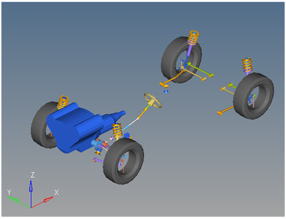
Figure 1. Swept Sine event
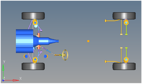
Figure 2. Top View of a Swept Sine event
Description
This event is designed to work with a full vehicle model that has been built through the MotionView Assembly Wizard. The event should attach to the model automatically when added through the Task Wizard. It can be used with models built manually, as long as the attachment scheme in the event is strictly followed.
A sinusoidal steering input at the steering wheel determines the frequency response characteristics of the vehicle. The vehicle velocity of 45 mph is kept constant throughout the event. After two seconds, the vehicle steers from its initial value to its maximum steering value, which is 45 degrees with a frequency increase rate of 0.2750 Hz/sec. This event covers a minimum frequency range of 0.25 to 3 Hz. This event helps to determine the steering wheel angle, yaw rate, roll angle, and lateral acceleration.
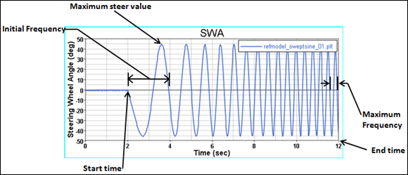
Figure 3.
Where,
θ = input steering wheel angle
θmax = maximum steer value
= initial steer frequency
= Frequency rate
time = Simulation time
`{ds_swept_sine.max_str.value}*DTOR
*STEP(TIME, {ds_swept_sine.st_tim.value}, 0.0, {ds_swept_sine.st_tim.value}+0.001, 1.0)
*SIN(2*PI
*(min({ds_swept_sine.max_frq.value},{ds_swept_sine.ini_frq.value}+(({ds_swept_sine.frq_rt.value}/2)
*(TIME-{ds_swept_sine.st_tim.value}))))*(TIME-{ds_swept_sine.st_tim.value}))`45*DTOR*STEP(TIME, 2, 0.0, 2+0.001, 1.0)*SIN(2*PI*(min(3,0.25+((0.275/2)*(TIME-2))))*(TIME-2))
|
ds_swept_sine.max_str.value is the symbolic
representation of the maximum steer values from the dataset
named “ds_swept_sine”, found in the Swept sine event.
.value indicates the input value should be
used in the expression. DTOR is the conversion
factor from degrees to radians. |
|
The STEP function evaluates to zero before
ds_swept_sine.st_tim.value (swept sine
start time) and evaluates to one when the solution time is
(swept sinestart time + .001). The step is used to transition
from a zero steering wheel angle to the increasing frequency
sine wave. |
|
The sin(2*PI takes the sin of the remainder
of the equation. 2*PI converts frequency to
radians. |
|
The min function takes the minimum of either
the maximum frequency value or the product of the two. |
Note that the maximum frequency is a frequency limit only. The actual maximum frequency obtained in the simulation is a function of the Initial frequency, the frequency rate, and the start and end time. The steering wheel sine wave begins at the initial frequency at the start time and increases by the frequency rate each second until the event ends at the end time. The maximum frequency only comes in to effect if the end time is mismatched with the frequency rate.
Six types of modeling element containers are used to define the event. Two sub systems (a drive torque controller and output requests) are also included during the event.
Attachments
The event uses the standard event attachment. The attachments resolve automatically if the model is built through the Model Wizard. The attachments contain the minimum data the event needs to run the analysis. The attachments are standard for most events.Datasets
One dataset is used in the system, which contains the data used to describe the Swept sine event. The event allows you to set the initial Vehicle velocity, Initial And Maximum steer value, Initial and Maximum frequency, Frequency rate, Start time, End time and Time step. The wheel rotational velocities and ground height are calculated values and should not be changed.Forms
The Form is the only place that you should change the Swept sine event. Initial Vehicle velocity, Initial steer value, Maximum steer value, Initial frequency, Maximum frequency, Frequency rate, Start time, End time and Time step are the parameters that can be changed. The wheel rotational velocities are calculated values and should not be changed.Joints
A ball joint is included in the Swept sine event. The joint attaches a dummy body to the steering rack. The joint is included to make certain events work in ADAMS. Attach the dummy body to the steering rack if building a model manually.Motions
Three motions are included in the event. The steering motion is used in the template which gives the input for the vehicle to steer and acts on a revolute joint that connects the steering wheel to the vehicle body. If a steering column is not included in the model, the motion acts on the joint between the steering rack input shaft and the vehicle body.
The Front and Rear Wheel Motions act on the wheel spindle revolute joints that connect the wheel hub to the knuckle. The motion is initially zero (fixing the wheels to the knuckle) so the model converges statically. The wheel locking motions get deactivated after the convergence of the static analysis to allow the tires to rotate during dynamic analysis.
Solver Variables
The Swept sine consists of only one solver variable, the Swept Sine Variable, which is an expression. It is used in the templates.Templates
A template is included in the Swept sine event task. The template is solver specific and only the MotionSolve template is documented. The template is inserted in the solver deck after the </Model> command and controls the execution of the event.<ResOutput
angle_type = "YPR"
/>
<ResOutput
mrf_file = "TRUE"
/>
<ResOutput
plt_file = "TRUE"
/>
<H3DOutput
switch_on = "TRUE"
increment = "1"
/>
<ResOutput
abf_file = "TRUE"
/>
{if (tire_dataset.opt_omega.ival ==1)}
<!--Initial static analysis -->
<Simulate
analysis_type = "Static"
end_time = "0.0"
/>
{endif}
<Deactivate
element_type = "MOTION"
element_id = "{mot_frnt_wheel.l.idstring}"
/>
<Deactivate
element_type = "MOTION"
element_id = "{mot_frnt_wheel.r.idstring}"
/>
<Deactivate
element_type = "MOTION"
element_id = "{mot_rear_wheel.l.idstring}"
/>
<Deactivate
element_type = "MOTION"
element_id = "{mot_rear_wheel.r.idstring}"
/>
{if (tire_dataset.opt_omega.ival ==2)}
<!--Initial static analysis -->
<Simulate
analysis_type = "Static"
end_time = "0.0"
/>
{endif}
<Deactivate
element_type = "JPRIM"
element_id = "{j_clamp_1_body.idstring}"
/>
<Deactivate
element_type = "JPRIM"
element_id = "{j_clamp_2_body.idstring}"
/>
{if ds.inp_type.value == "Angle"}
<Deactivate
element_type = "FORCE"
element_id = "{tor_str.idstring}"
/>
<Motion_Joint
id = "{wh_motion.idstring}"
expr = "IF(TIME-.5:{-ds.str_mag.value}D*STEP(TIME,0,0,0.001,1),{-ds.str_mag.value}D,{-ds.str_rate.value}D*(TIME-.5)-{ds.str_mag.value}D)"
/>
<Simulate
analysis_type = "Transient"
end_time = "{(ds.max_str.value-ds.str_mag.value)/ds.str_rate.value+.5}"
num_steps = "{((ds.max_str.value-ds.str_mag.value)/ds.str_rate.value+.5)*100}"
/>
{else}
<Deactivate
element_type = "MOTION"
element_id = "{wh_motion.idstring}"
/>
<Force_Scalar_TwoBody
id = "{tor_str.idstring}"
type = "Torque"
val_expression = "IF(TIME-.5:{-ds.str_mag.value},{-ds.str_mag.value},{-ds.str_rate.value}*(TIME-.5)-{ds.str_mag.value})"
/>
<Simulate
analysis_type = "Transient"
end_time = "{(ds.max_str.value-ds.str_mag.value)/ds.str_rate.value+.5}"
num_steps = "{((ds.max_str.value-ds.str_mag.value)/ds.str_rate.value+.5)*100}"
/>
{endif}
<Stop/>References
ISO +7401-2003 - Road vehicles — Lateral transient response test methods — Open-loop test methods.