Quality Panel (Connectors)
Use the Quality panel to check the quality of connectors and the realized FE.
Location: Connectors module
The Quality panel is used to determine if the model contains duplicate connectors or if the realized elements meet the quality requirements such as the length of 1D elements and their perpendicularity to the shells they connect.
Connectors (Unrealized) Subpanel
| Option | Action |
|---|---|
| connectors | Select the connectors for which you would like to check the quality. |
| tolerance= | Specify the tolerance used to determine if connectors are considered duplicate or adjacent. |
| preview duplicates | Find all the duplicate connectors in the entire model that are within the tolerance of each other, highlight them in the modeling window (display is enabled if it was originally turned off), and place them in the input collector (ready to delete one of each pair of duplicates). |
| preview combine | Find all the adjacent connectors in the entire model that are within the tolerance of each other, highlight them in the modeling window (display is enabled if it was originally turned off), and place them in the input collector (ready to combine each set of adjacent connectors into one). |
| remove duplicates | Find all the duplicate connectors in the selected connectors and delete one of each pair of duplicates, thus eliminating any duplicates in the model. |
| combine | Combine each set of identical/congruent connectors into one connector that connects all the link entities. |
Projection Check Subpanel
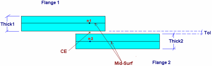
Figure 1. Correct Projection Length is the Distance Between n1 and n2
| Option | Action |
|---|---|
| connectors | Select the connectors for which you would like to check the projection length. |
| find too long/find too short/find too long or short | Select the type of error to check for.
|
| length = /length = (T1+T2)/2 | Define the projection length.
|
| tolerance | Specify a tolerance to find the weld that deviate from the projection length by more than this amount. The welds that deviate by this amount or less will be ignored. |
1D Elems Subpanel
| Option | Action |
|---|---|
| free 1Ds | Consider a 1D element free if one or more ends do not connect
to another element in the model. Note: This check is valid only
for mesh dependent realization types.
|
| length > | Fail 1D elements with a length greater than this value. |
| angle > | Fail 1D elements that deviate from the shell element normal by more than this value. |
| check | Perform all the selected checks and highlight the connectors for which 1D realization elements failed at least one of the selected quality checks. |
| save failed | Save the failed connectors (for which 1D realization elements failed at least one of the selected quality checks) to a mark so that you can retrieve them from other panels. |
3D Elems Subpanel
| Option | Action |
|---|---|
| length > | Fail hexa elements with a height greater than this value. |
| jacobian < | Fail hexa elements for which jacobian is lower than this
value. Jacobian is a measure of the deviation of an element from an ideally shaped element. The Jacobian value ranges from 0.0 to 1.0, where 1.0 represents a perfectly shaped element. Jacobian value of 0.7 and above is generally acceptable. |
| check | Perform all the selected checks and highlight the connectors for which hexa realization elements failed at least one of the selected quality checks. |
| save failed | Save the failed connectors (for which hexa realization elements failed at least one of the selected quality checks) to a mark so that you can retrieve them from other panels. |