Automesh Panel
Use the Automesh panel to generate a mesh of plate elements using surface geometry or existing shell elements to define the mesh area.
- Set the panel mode by selecting the appropriate subpanel.
- Select the meshing method by setting the entity selector to surfs or elems.
- Make the required element criteria settings.
- Set any algorithm options.
- Select the area to be meshed using the entity selector and any extended
selection methods. Tip: Click unmeshed and failed to make pre-defined surface selections if desired.
Size and Bias Subpanel
Use the Size and Bias subpanel to perform size and bias meshing, a flexible and powerful meshing method. A minimum of inputs are required for the element criteria settings. The algorithm options set preferences on how to handle certain situations when encountered in the geometry. When using existing finite elements as the basis for mesh generation, feature recognition settings allow the mesher to break up the areas defined by the selected elements into logical groupings with mesh controls set for each group boundary.
Size and Bias meshing works interactively or automatically. In interactive mode, manual control is presented via the Secondary Automesh panel during the mesh generation stage. Interactive meshing allows you to control mesh size and element type, and to set different mesh generation algorithms and test element quality on a surface-by-surface basis. The resulting modified mesh can be updated at any time, giving immediate feedback as to the effectiveness of the change. When meshing in the automatic mode, the mesh will be generated using only the settings, criteria and options set in the Automesh panel.
| Option | Action | ||||||
|---|---|---|---|---|---|---|---|
| entity selector | Select surfaces or existing finite elements to define the area to mesh. | ||||||
| features |
When using existing finite elements as a basis for
automeshing, feature recognition is used to define logical faces. Select how the
automesher treats features.
|
||||||
| interactive/automatic |
|
||||||
| element size | Enter a floating point numeric value for the average element size. The length of any active (shared or free) surface edge will be divided by this number to determine the number of elements to place along that edge. | ||||||
| mesh type |
Select the type of element to use during mesh creation.
|
||||||
| mapped type | Select the type of elements to use for surfaces that can be mapped to simple geometric shapes. | ||||||
| free type | Select the type of elements to use for surfaces that cannot be mapped to simple geometric shapes. | ||||||
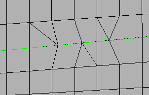
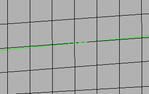
| feature angle |
Define a maximum angle across which elements can be
maintained.
Note: Any time two adjacent elements’ normals would exceed this
angle, a new set of nodes is created between them to maintain clean feature
lines. Using a higher value results in elements spanning the feature
line.
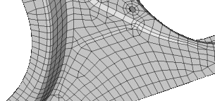 Figure 10. Feature Lines Preserved. With an appropriate value, the features lines are preserved. 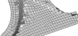 Figure 11. Feature Lines Blurred. If the feature angle is too high, the feature lines are blurred. |
||||||
| vertex angle |
Define the angle used for breaking feature-edges into simpler segments. |
||||||
| elems to surf comp/elems to current comp | Select the destination component for the newly created elements as the “current” active component or the component to which the surface belongs. | ||||||
| first order/second order |
|
||||||
| connectivity |
Select how the connectivity between the newly
created elements and any adjacent existing elements will be handled.
|
||||||
| flow: align |
Produce a more orthogonal quad-dominant mesh.
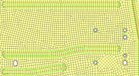 Figure 12. No Flow Alignment 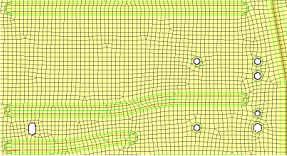 Figure 13. Flow Alignment. Flow alignment is used, producing straighter rows of elements. |
||||||
| flow: size |
Enforces a global mesh element size with minimal min/max
element size variation.
Important: Only available when flow: align is
selected.
|
||||||
| map: size | Keep the elements roughly the same size. | ||||||
| map: skew | Prevent the mesh from producing highly-skewed elements. | ||||||
| anchor nodes | Designate nodes that will remain and be reused in the new mesh. Anchor nodes are "fixed" so that the automesher cannot move or replace them; in essence, they are exceptions to the re-meshing operation, and the new mesh must utilize them. | ||||||
| link opposite edges with AR < |
Link mesh settings on opposing edges of rectangular
surfaces. Use the toggle to define the maximum aspect ratio (AR) to allow between
large and small edge sizes of linked edges. auto corresponds to a value of 2.11.
Increasing the value will add more surfaces to the linked chain, whereas decreasing
the value will remove some surfaces from the linked chain.
|
Batchmesh/QI Optimize Subpanel
Use the Batchmesh/QI Optimize subpanel to perform Quality Index meshing, an iterative automatic mesh generation method driven by element quality criteria. During the mesh generation process, the quality index of the mesh is determined by evaluating each element against a set of element quality tests. If all required element quality criteria are passed, then that element has a perfect quality index of zero. As the element quality deteriorates, the quality index value increases; a lower quality index score indicates an element more closely meets the ideal quality requirements.
| Option | Action | ||||||
|---|---|---|---|---|---|---|---|
| batchmesh/QI optimize | Switch between QI optimize meshing parameters and BatchMesh parameters. | ||||||
| entity selector | Select surfaces or existing finite elements to define the area to mesh. | ||||||
| features |
When using existing finite elements as a basis for
automeshing, feature recognition is used to define logical faces. Select how the
automesher treats features.
|
||||||
| element size | Enter a floating point numeric value for the average element size. The length of any active (shared or free) surface edge will be divided by this number to determine the number of elements to place along that edge. | ||||||
| mesh type |
Select the type of element to use during mesh creation.
|
||||||
| use current criteria/criteria file | Switch between using the current element quality criteria or use a custom criteria file. | ||||||
| edit criteria | Open the Criteria File Editor. Important: Only
available when user current criteria is
selected.
|
||||||
| feature angle |
Define a maximum angle across which elements can be
maintained.
Note: Any time two adjacent elements’ normals would exceed this
angle, a new set of nodes is created between them to maintain clean feature
lines. Using a higher value results in elements spanning the feature
line.
Figure 26. Feature Lines Preserved. With an appropriate value, the features lines are preserved. Figure 27. Feature Lines Blurred. If the feature angle is too high, the feature lines are blurred. |
||||||
| vertex angle |
Define the angle used for breaking feature-edges into simpler segments. |
||||||
| smooth across common edges with | Node smoothing moves nodes across adjacent surface edges whose feature angle is less than the value specified. When selected, strict adherence to the geometry of the surface edges in not enforced for non-feature edges; some deviation from the geometry can occur. | ||||||
| elems to surf comp/elems to current comp | Select the destination component for the newly created elements as the “current” active component or the component to which the surface belongs. | ||||||
| first order/second order |
|
||||||
| connectivity |
Select how the connectivity between the newly
created elements and any adjacent existing elements will be handled.
|
||||||
| flow: align |
Produce a more orthogonal quad-dominant mesh.
Figure 28. No Flow Alignment Figure 29. Flow Alignment. Flow alignment is used, producing straighter rows of elements. |
||||||
| flow: size |
Enforces a global mesh element size with minimal min/max
element size variation.
Important: Only available when flow: align is
selected.
|
||||||
| anchor nodes | Designate nodes that will remain and be reused in the new mesh. Anchor nodes are "fixed" so that the automesher cannot move or replace them; in essence, they are exceptions to the re-meshing operation, and the new mesh must utilize them. | ||||||
| preserve edges | Open the Preserve Edges tool and define settings to ensure that specific component edges and feature lines do not accidentally get discarded during auto cleanup or batch meshing. |
Edge Deviation Subpanel
Use the Edge Deviation subpanel to set specific meshing parameters to limit how far the mesh elements can deviate from the actual edges of the surfaces meshed, or when in the case of re-meshing elements, deviation from inferred edges based on features.
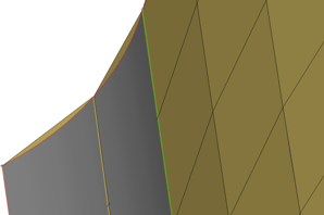
Figure 30. Meshing Curved Surfaces. The planar elements (tan color) can deviate from the curved grey geometry.
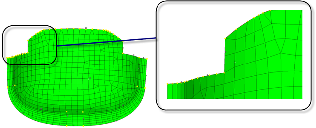
Figure 31. Example: Edge Deviation. Edge deviation control when meshing creates smaller elements, and spaces nodes closer together to limit how much the elements can deviate from the surface edges.
| Option | Action | ||||||
|---|---|---|---|---|---|---|---|
| entity selector | Select surfaces or existing finite elements to define the area to mesh. | ||||||
| features |
When using existing finite elements as a basis for
automeshing, feature recognition is used to define logical faces. Select how the
automesher treats features.
|
||||||
| interactive/automatic |
|
||||||
| min/max element size |
Define element size boundaries.
Note: The values specified
here are rigidly enforced, even if other settings (that is max deviation) are
violated.
|
||||||
| max deviation | Define an allowable deviation between the element edge and the surface edge. To meet this requirement, element edge lengths along a curved surface edge are reduced as needed down to a lower limit set by the min elem size field. | ||||||
| max angle | Define the maximum allowable angle between two element edges.
This helps determine the size of an element to create; if the angle formed by adjacent element edges would exceed this value, smaller elements are tried until the angle is equal to or less than this value. |
||||||
| mesh type |
Select the type of element to use during mesh creation.
|
||||||
| mapped type | Select the type of elements to use for surfaces that can be mapped to simple geometric shapes. | ||||||
| free type | Select the type of elements to use for surfaces that cannot be mapped to simple geometric shapes. | ||||||
| feature angle |
Define a maximum angle across which elements can be
maintained.
Note: Any time two adjacent elements’ normals would exceed this
angle, a new set of nodes is created between them to maintain clean feature
lines. Using a higher value results in elements spanning the feature
line.
Figure 41. Feature Lines Preserved. With an appropriate value, the features lines are preserved. Figure 42. Feature Lines Blurred. If the feature angle is too high, the feature lines are blurred. |
||||||
| vertex angle |
Define the angle used for breaking feature-edges into simpler segments. |
||||||
| elems to surf comp/elems to current comp | Select the destination component for the newly created elements as the “current” active component or the component to which the surface belongs. | ||||||
| first order/second order |
|
||||||
| connectivity |
Select how the connectivity between the newly
created elements and any adjacent existing elements will be handled.
|
||||||
| flow: align |
Produce a more orthogonal quad-dominant mesh.
Figure 43. No Flow Alignment Figure 44. Flow Alignment. Flow alignment is used, producing straighter rows of elements. |
||||||
| flow: size |
Enforces a global mesh element size with minimal min/max
element size variation.
Important: Only available when flow: align is
selected.
|
||||||
| map: size | Keep the elements roughly the same size. | ||||||
| map: skew | Prevent the mesh from producing highly-skewed elements. | ||||||
| link opposite edges with AR < |
Link mesh settings on opposing edges of rectangular
surfaces. Use the toggle to define the maximum aspect ratio (AR) to allow between
large and small edge sizes of linked edges. auto corresponds to a value of 2.11.
Increasing the value will add more surfaces to the linked chain, whereas decreasing
the value will remove some surfaces from the linked chain.
|
||||||
| anchor nodes | Designate nodes that will remain and be reused in the new mesh. Anchor nodes are "fixed" so that the automesher cannot move or replace them; in essence, they are exceptions to the re-meshing operation, and the new mesh must utilize them. |
Surface Deviation Subpanel
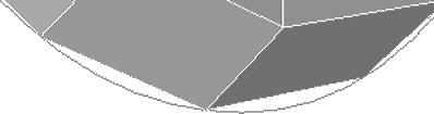
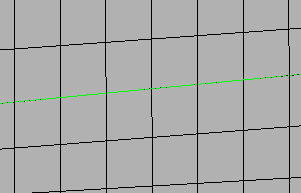
Figure 48. Surface Deviation. A gap is visible between the curved edge of the surface and the element edges.
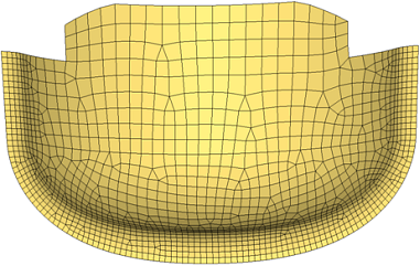
Figure 49. Surface Deviation Meshing. Smaller elements are used to accurately represent curved surfaces. Larger elements are used where the geometry shows less curvature.
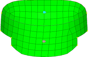
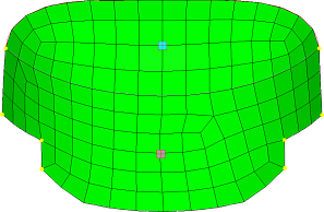
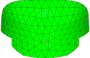
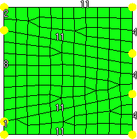
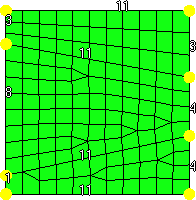
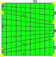
Surface Deviation meshing only works in an automatic mode; interactive meshing with the Secondary Automesh panel is not possible. However, use the refine function to set a specific desired mesh size for a point, line or surface face. This option accesses another temporary subpanel that is secondary to the Surface Deviation subpanel. From this subpanel, select fixed points, lines, or surfaces to define an area in which you desire a more refined mesh. You can specify a different element size for these areas, which displays as a color-coded numeric value: yellow for points, green for lines, or red for surfaces. An option to show all or show active toggles the view of these numeric values; show active displays only the refinement value for the most recently selected point, line or surface, while show all shows all values for all selected entities.
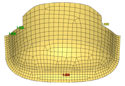
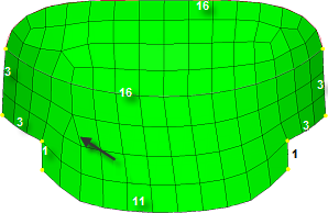
Figure 50. Surface Deviation, Refinement Not Applied. The colored numbers indicate refinement targets: point (yellow), line (green), and surface (red).
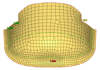
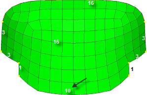
Figure 51. Surface Deviation, Refinement Applied. The mesh is finer near the point (yellow), along the line/edge (green), and on the surface (red).
| Option | Action |
|---|---|
| entity selector | Select surfaces or existing finite elements to define the area to mesh. |
| element size | Enter a floating point numeric value for the average element size. The length of any active (shared or free) surface edge will be divided by this number to determine the number of elements to place along that edge. |
| growth rate | Determine how rapidly elements can increase in size as they
are created further and further away from features.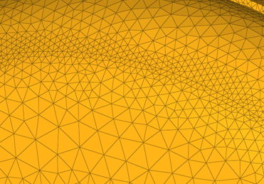 Figure 52. Example: Growth Rate. Elements further from the features grow larger with each row. |
| min element size | Elements with edges smaller than this value will not be created. |
| span angle | Controls the element size at curve input. The smaller the
angle, the more refined curvature will be and the more preserved
the input shape will be. By default span angle is 25.0
degrees. Important: Valid only for element-based
surface deviation.
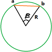 Figure 53. Example: Span Angle. β is the span angle of the edge ab. The length of ab is less than 2R( sin β/2 ). |
| feature angle |
Define a maximum angle across which elements can be
maintained.
Note: Any time two adjacent elements’ normals would exceed this
angle, a new set of nodes is created between them to maintain clean feature
lines. Using a higher value results in elements spanning the feature
line.
Figure 54. Feature Lines Preserved. With an appropriate value, the features lines are preserved. Figure 55. Feature Lines Blurred. If the feature angle is too high, the feature lines are blurred. |
| max deviation | Define an allowable deviation between the element edge and the surface edge. To meet this requirement, element edge lengths along a curved surface edge are reduced as needed down to a lower limit set by the min elem size field. |
| mesh type |
Select the type of element to use during mesh creation.
|
| mapped type | Select the type of elements to use for surfaces that can be mapped to simple geometric shapes. |
| free type | Select the type of elements to use for surfaces that cannot be mapped to simple geometric shapes. |
| elems to surf comp/elems to current comp | Select the destination component for the newly created elements as the “current” active component or the component to which the surface belongs. |
| first order/second order |
|
| connectivity |
Select how the connectivity between the newly
created elements and any adjacent existing elements will be handled.
|
| closed volume proximity | Dynamically create finer mesh across the narrow spaces between features in a closed volume/solid entity. |
| free edge deviation | Produce a finer mesh around curved edges (such as holes) even
on planar surfaces. Clear this checkbox to base the mesh on surface chordal deviation only. |
| refine | Open a temporary subpanel, from which you can perform mesh
refinement on or around specific points, lines, or
surfaces. Use the switch to select the type of entity to use as a basis, then select the points/lines/surfaces and specify an element size in the numeric box. |
| show refined | If you use refine to perform localized mesh refinement, this checkbox displays the refinement element size you assigned to each entity marked for refinement. |
Rigid Body Mesh Subpanel
Rigid bodies are surfaces that are expected to be treated as undeformable in the solution. One example of a rigid body is in metal-forming. When modeling the results of a die pressing down on a metal sheet, it's important to model the shape of the die because that determines the shape of the metal sheet after being pressed. However, during a forming analysis the stresses and deformations of the die itself are not of interest, only those of the formed metal sheet. Other applications for rigid bodies include the impactors used in vehicle crash simulation.
A mesh that accurately represents the rigid geometry is important for such simulations to allow the solver collision detection routines to work effectively and accurately. Since stress and deformation of the rigid body are not calculated by the solver, the rigid body mesh focuses on accurately modeling the shape of the body rather than on producing a high-quality mesh. To this end, it uses the same faceting and shading routines that are used for drawing the model graphics. The resulting mesh may have high aspect ratio or extremely tapered elements that would not be suitable for solution, but can accurately represent the geometry.
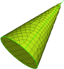
Figure 61. Cone with Surface Deviation Based Mesh. Many small elements are required to capture the geometry, even so, the elements exhibit a lot of warpage and those at the tip are distorted and do not accurately represent the geometry.
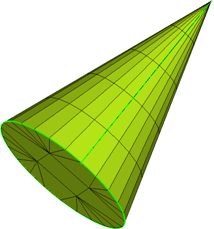
Figure 62. Cone with Rigid Body Mesh. The shape of the object can be accurately modeled using fewer larger elements since the element shape is not a concern.
| Option | Action |
|---|---|
| entity selector | Select surfaces or existing finite elements to define the area to mesh. |
| min/max element size |
Define element size boundaries.
Note: The values specified
here are rigidly enforced, even if other settings (that is max deviation) are
violated.
|
| max deviation | Define an allowable deviation between the element edge and the surface edge. To meet this requirement, element edge lengths along a curved surface edge are reduced as needed down to a lower limit set by the min elem size field. |
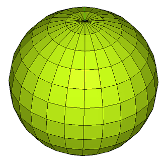
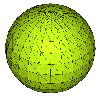
| max feature angle | Define a maximum allowable break angle between adjacent
elements. The element size is adjusted such that the angle
between the normals of adjacent elements does not exceed this
value.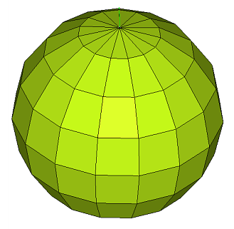 Figure 63. . The minimum and maximum element sizes are 3 and 50 respectively. The mesh is constrained by the max deviation value set to 0.5. The element size is set such that the maximum distance between the element and the spherical surface does not exceed this setting. 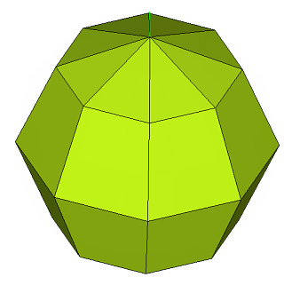 Figure 64. . The minimum and maximum element sizes are 3 and 50 respectively. The deviation setting is relaxed to 3.0, and the mesh is bound by the maximum feature angle setting of 45 degrees. |
| mesh type | Select the type of element to use during mesh creation.
|