Nodes Panel
Use the Nodes panel to create nodes using a wide variety of methods.
Location: Geom page
 XYZ Subpanel
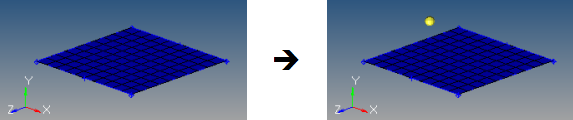
Figure 1. Coordinates of the Created Node are X=5, Y=4, and Z=8
- Manually enter the coordinate values in the x, y, and z fields.
- Use the x, y, z selectors to populate the x, y, and z values by selecting nodes in the modeling window. Upon selecting a node, the respective x, y, or z coordinate value is automatically displayed in the corresponding field. The values can be edited as desired.
- Use the as node selector to populate the coordinate and system values by selecting a node in the modeling window. Upon selecting a node, the respective x, y and z coordinate values and the reference system value from the selected node is automatically displayed in the corresponding field. The values can be edited as desired.
 On Geometry Subpanel
By default, nodes are created relative to the global system, however a local coordinate system can be specified using the system selector. This system can be rectangular, cylindrical or spherical. When a node is created, it is also assigned to the specified reference system. The node is then updated to reflect any changes that are made to that system (for example translate, rotate).
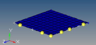
Figure 2. Nodes Created on Lines. Nodes are created on the lines bordering a surface.
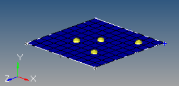
Figure 3. Nodes Created on Surfaces
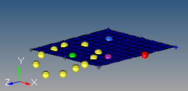
Figure 4. Nodes Created on a Plane. The plane is invisible, but coincide with the visible surface.
 Arc Center Subpanel
Use the Arc Center subpanel to create a node at the center of the arc that best approximates the input set of nodes, points, or lines.
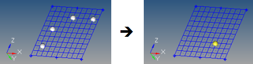
Figure 5.
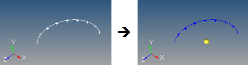
Figure 6.
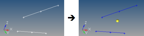
Figure 7.
An optional tolerance is available to verify whether the calculated best-fit circle is sufficient. If ignored, the best-fit circle is always calculated; otherwise, an error is returned if the input entities are not all on the circle within the specified tolerance.
 Extract Parametric Subpanel
Use the Extract Parametric subpanel to create nodes at parametric locations on lines and surfaces.
- 0.0 <= u lower bound <= u upper bound <= 1.0.
- If the lower and upper bounds are the same, only one node is created.
- If the number of u nodes is specified as 1, only the lower bound is used.
- The line parameterization type can be specified as either arc length or internal. Internal parameterizations depend on how the line was originally created, while arc length simply distributes the nodes uniformly.
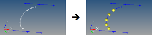
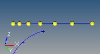
Figure 8. Nodes Created on a Line. This example uses u lower bound 0, u upper bound 0.75, u nodes = 5, and arc length parameterization.
- 0.0 <= u lower bound <= u upper bound <= 1.0.
- 0.0 <= v lower bound <= v upper bound <= 1.0.
- The number of u and v nodes must be >= 1.
- The total number of nodes created equals (number of u nodes * number of v nodes).
- The surface parametric area is scaled to the visible surface area. Nodes will be created inside the visible surface area.
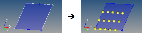
Figure 9. Nodes Created on a Surface. In this example, u ranges from 0 to 0.75 with 5 nodes, while v ranges from 0 to 0.66 with 3 nodes.
 Extract on Line Subpanel
Use the Extract on Line subpanel to create evenly spaced or biased nodes on a selection of lines.
 Interpolate Nodes Subpanel
Use the Interpolate Nodes subpanel to create evenly spaced or biased nodes by interpolating between existing nodes in space.
The input nodes are specified as a node list, with each node considered as a pair with the next node in the list. The specified number of nodes are created on a straight line between each node pair.
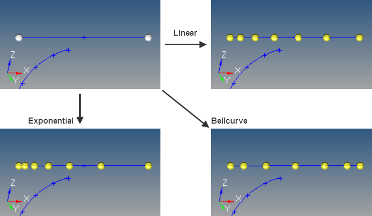
Figure 13.
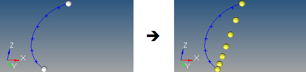
Figure 14.
To interpolate nodes along a curved line, use the Interpolate on Line subpanel instead.
 Interpolate on Line Subpanel
Use the Interpolate on Line subpanel to create evenly spaced or biased nodes by interpolating between existing nodes on a line.
The input nodes are specified as a node list, with each node considered as a pair with the next node in the list. The nodes are created on the input line between each node pair.
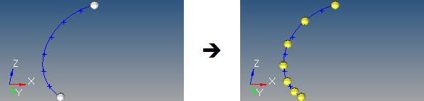
Figure 15. Nodes Interpolated along a Line. 5 nodes created between 2 input nodes along a curved line, using linear biasing.
 Interpolate on Surface Subpanel
Use the Interpolate on Surface subpanel to create evenly spaced or biased nodes by interpolating between existing nodes on a surface.
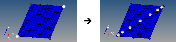
Figure 16. Nodes Interpolated on a Surface. The highlighted opposing corner nodes have 7 interpolated nodes created between them, using Bellcurve biasing.
The nodes are not required to lie on the selected surface, as all input nodes are first projected onto the surface.
 Intersect Subpanel
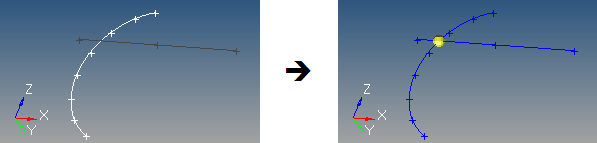
Figure 17. Node Created at Each Intersection Location
For surface, solid, and plane intersections, if the input line or vector lies on the surface/solid/plane the result is undefined and unpredictable.
For vectors, the magnitude and direction of the vector do not have any effect on the result. The vector extends through the entire model space.