Distance Panel
Use the Distance panel to determine the distance between two nodes/points or the angle between three nodes/points, or to change distances or angles.
Location: Geom page
When switching between subpanels your settings will not be reverted, but in some cases your selections may be affected. Each subpanel has selection criteria as well as distance displays which are populated as soon as points or nodes are selected. However, the distance displays can also be manually changed to move the selected nodes or points.
You can measure the distance between two nodes/points by specifying the two nodes/points; the total distance between the nodes/points, and the x, y, and z distances are displayed.
If you want to change the distance between two nodes/points, you can change the total distance, or any of the x, y, or z component values. The total distance will be recalculated if you have changed any of the x, y, or z component values. After you have changed the desired values, Engineering Solutions follows the initial vector and relocates the second node/point at the specified distance along that vector. The node selected as N1 will remain fixed, only the N2 node will be moved.
You can also determine the existing angle between three nodes/points. After you have selected the three nodes/points, the value of the angle is displayed.
You can change the angle between three nodes/points (where three nodes/points, N1, N2, and N3 define a plane, with N2 as the center) by specifying the three nodes/points and supplying the desired angle. After you have given the new value for the angle, Engineering Solutions moves N3 along the arc formed by swinging N3 around N2, until the angle is equal to the one you specified.
Any modifications of the node or point positions are always made in the global rectangular coordinate system, regardless of the measurement system used.
Distance between Two Nodes
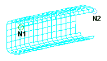
Figure 1. Distance between Two Nodes
Distance between Three Points
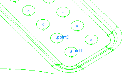
Figure 2. Distance between Three Points
Angle between Three Nodes
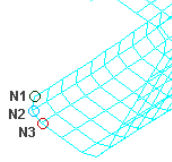
Figure 3. Angle between Three Nodes
Angle between Three Points
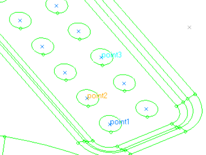
Figure 4. Angle between Three Points
Two Nodes Subpanel
| Option | Action |
|---|---|
| N1 / N2 | Select the first and second nodes you wish to measure between. |
| syst | Specify the coordinate system within which to measure the distances and angles. The selected coordinate system affects the measured values only. If a non-rectangular coordinate system is selected, the meaning of the X,Y and Z component distances will change accordingly, although the field labels will not be changed. |
| distance | Specify the total distance covered by the selected set of nodes or points. |
| x, y, z dist | Specify the X, Y, and Z direction component distance between the selected nodes or points. |
| angle | Specify the angle formed by the three nodes or points, using node/point 2 as the angle vertex such that a straight vector equals 180 degrees. |
| nodes between | Specify the number of nodes/points you wish to create, which will be evenly spaced along the vector between the first and second selected nodes. |
Three Nodes Subpanel
| Option | Action |
|---|---|
| N1 / N2 / N3 | Select the first, second and third nodes you wish to measure between. |
| syst | Specify the coordinate system within which to measure the distances and angles. The selected coordinate system affects the measured values only. If a non-rectangular coordinate system is selected, the meaning of the X,Y and Z component distances will change accordingly, although the field labels will not be changed. |
| distance | Specify the total distance covered by the selected set of nodes or points. |
| x, y, z dist | Specify the X, Y, and Z direction component distance between the selected nodes or points. |
| angle | Specify the angle formed by the three nodes or points, using node/point 2 as the angle vertex such that a straight vector equals 180 degrees. |
| radius | The radius of the circle going through the three selected nodes. This field is read-only; you cannot edit the value displayed. |
| nodes between | Specify the number of nodes/points you wish to create, which will be evenly spaced along the vector between the first and second selected nodes. |
Two Points Subpanel
| Option | Action |
|---|---|
| point 1 / point 2 | Select the first and second points you wish to measure between. |
| syst | Specify the coordinate system within which to measure the distances and angles. The selected coordinate system affects the measured values only. If a non-rectangular coordinate system is selected, the meaning of the X,Y and Z component distances will change accordingly, although the field labels will not be changed. |
| distance | Specify the total distance covered by the selected set of nodes or points. |
| x, y, z dist | Specify the X, Y, and Z direction component distance between the selected nodes or points. |
| angle | Specify the angle formed by the three nodes or points, using node/point 2 as the angle vertex such that a straight vector equals 180 degrees. |
| points between | Specify the number of nodes/points you wish to create, which will be evenly spaced along the vector between the first and second selected nodes. |
Three Points Subpanel
| Option | Action |
|---|---|
| point 1 / point 2 / point 3 | Select the first, second and third points you wish to measure between. |
| syst | Specify the coordinate system within which to measure the distances and angles. The selected coordinate system affects the measured values only. If a non-rectangular coordinate system is selected, the meaning of the X,Y and Z component distances will change accordingly, although the field labels will not be changed. |
| distance | Specify the total distance covered by the selected set of nodes or points. |
| x, y, z dist | Specify the X, Y, and Z direction component distance between the selected nodes or points. |
| angle | Specify the angle formed by the three nodes or points, using node/point 2 as the angle vertex such that a straight vector equals 180 degrees. |
| radius | Specify the number of nodes/points you wish to create, which will be evenly spaced along the vector between the first and second selected nodes. |
| points between | Specify the number of nodes/points you wish to create, which will be evenly spaced along the vector between the first and second selected nodes. |
Command Buttons
| Button | Action |
|---|---|
| reject | Revert the most recent change made, whether in distance or points/nodes between. |
| nodes between | Create the number of nodes specified by the nodes between = field between the selected nodes. |
| circle center | Create a best-fit circle using the three selected nodes/points as input, and then generate a new visible node or point at the circle's center. |
| points between | Create the number of points specified by the points between = field between the selected nodes. |
| return | Exit the panel. |