Tetramesh Panel
Use the Tetramesh panel to fill an enclosed volume with first or second order tetrahedral elements.
Location: 3D page
A region is considered enclosed if it is entirely bounded by a shell mesh (tria and/or quad elements). Other element configurations generated in this panel are hexahedral, wedge, and pyramids. These elements are typically generated when you need boundary layer type meshes on certain areas of the volume surface.
Tetra Mesh Subpanel
Use the Tetra Mesh subpanel to fill an arbitrary volume, defined by its surface using tria/quad elements, with tetrahedral elements.
Tetra Remesh Subpanel
Use the Tetra Remesh subpanel to regenerate the mesh for a single volume of tetrahedral elements.
- fixed
- Fix the free boundary faces.
- swappable
- Swapp the edges of the free boundary faces. The mesh nodes stay unchanged.
- remeshable
- Remesh the free boundary faces.
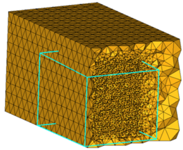 Figure 1. Fixed |
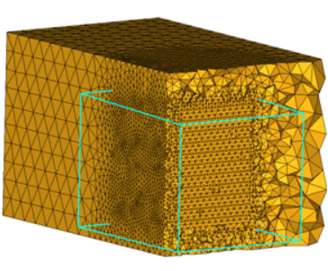 Figure 2. Remeshable |
Volume Tetra Subpanel
Use the Volume Tetra subpanel to generate a shell mesh and fill the enclosed volume with solid elements.
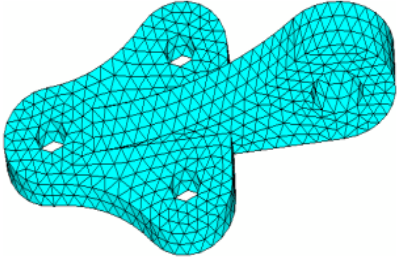 Figure 3. Without Proximity |
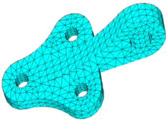
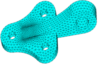 Figure 4. With Proximity |
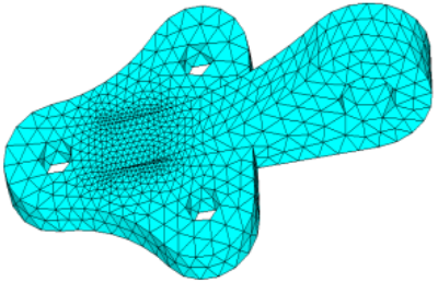 Figure 5. With Proximity |
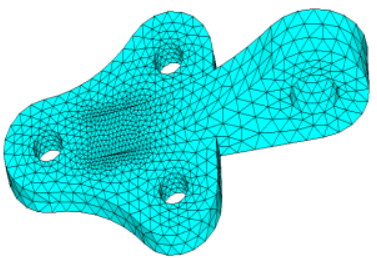 Figure 6. With Proximity and Curvature |
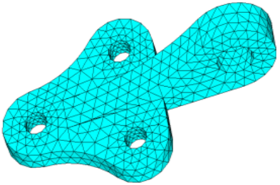 Figure 7. Triangular 2D Elements |
 |
Element order can be defined as first or second. Existing elements will be used if the order of the elements are the same as the defined tetramesh element order. Meshing will fail if the shell elements of solids are present and are conflicting with the selection.
If you want to apply an extra stage of calculation to improve the overall mesh quality by removing some nodes and combining elements, select the Cleanup elements checkbox.
Tetramesh Parameters Subpanel
| Option | Action |
|---|---|
| Max tetra size | Specify a size that tetra elements will not exceed in any dimension. |
| Optimize Mesh Quality / TetraMesh Normally / Optimize Mesh Speed |
|
| Standard / Aggressive / Gradual /Interpolate / User Controlled/ Octree based / Delaunay | Select a method for
defining the growth rate of elements beyond the initial uniform
layers (boundary layers). These growth options control the
tradeoff between the number of elements generated and the
element quality.
|
| Uniform Layers |
Select how far the constant tetra size should be maintained from the surface mesh during tetrameshing. The distance is internally calculated by multiplying the user defined factor by the local surface mesh size.Engineering Solutions specifies different default value of this parameter.
|
| Growth rate |
If d is the initial thickness and r is the initial growth rate, then the thicknesses of the successive layers are d, d*r, d*r^2, d*r^3, d*r^4, and so on. If element quality is very important and you are not concerned with the total number of elements created, then Interpolate will produce the best results because the element size changes smoothly and therefore the element quality is better. Engineering Solutions specifies different default value of this parameter.
|
| Pyramid transition ratio | Specify the relative height of pyramid elements used for the transition from hexa elements in the boundary layer to the tetra elements in the core. |
| Export settings | Save the settings to a file. |
| Refinement box | Specify the refinement boxes which should be considered during volume meshing. Refinement boxes not selected will be ignored. |
| smoothing | Apply an extra stage of calculation to improve overall mesh quality. Additional smoothing and swapping steps will be performed and tetra elements will be split to achieve a smoother mesh transition. If tetra elements are used in the boundary layer those elements will be excluded from smoothing to maintain the original distribution. |
| Number of Layers |
Specify the number of tetrahedral layers to generate. The
Tetramesher ensures the tetracore contains, at minimum, the specified number of
tetra layers in the model. This functionality ensures a certain mesh resolution in
case of close proximity or thin channels. When generating multiple tetrahedral
layers, keep the following restrictions in mind:
|
| fill voids | Mesh all volumes, if your geometry includes volumes inside of another volume. For example if you had a sphere inside of a larger sphere, checking this option would cause the volume of the inner sphere as well as the volume between the two spheres to be meshed. |
| Fix Midnodes | In case of 2nd order tetras, this option fixes the mid edge node of surface mesh while volume meshing |
| Elem quality target | Select an element criteria and a threshold. After the tetrameshing step, Engineering Solutions performs a mesh optimization step to fulfill the defined threshold for the selected element criteria. |
| Min Tetra Height | Generate tetramesh with a minimum height above the value defined. The tetramesh algorithm will try to enforce the user-defined minimum height. |
| Min Tetra Size | Generate tetramesh with a minimum size above the value defined. The tetramesh algorithm will try to enforce the user-defined minimum size. |
Refinement Box Subpanel
Use the Refinement Box subpanel to define a specific box-shaped volume within an existing tetramesh in which to generate finer mesh.
You can specify some elements to be fixed, and others to be floatable. A fixed tria-quad element is one that must be exactly represented as a face of a tetra/penta-pyramid/hexa element in the final mesh. A floatable element is one whose nodes locations are used, but the exact connectivity of those nodes can be modified if it produces a better mesh. Unless you need a special mesh type, for example surface layers of pentas/hexas, you should select as fixed only those elements that must match a pre-existing mesh, leaving the rest floatable. If the bounding surface contains quad elements, and if these quad elements are defined as fixed elements, then a first layer of elements is generated on the boundary, and pyramid elements are generated from the quad faces. However, when quad elements are defined as float elements, they are split into two trias, and the tetra meshing proceeds normally.
You can also specify various growth options in order to control the tradeoff between the number of tetras generated and their quality. Higher, more aggressive growth rates produce fewer elements, but they may be of poorer quality.
The Tetramesh panel allows you to choose from three different mesh generation priorities. The generate mesh normally option applies in most cases, but if your solver is particularly sensitive to element quality, use the optimize element quality option. This directs the tetramesher to spend more time trying to generate better quality elements. In particular, it employs the volumetric ratio (CFD "skew") measurement for rating potential tetras. For some applications, element quality considerations are less important than mesh generation time. In those cases, choose the optimize meshing speed option.
| Option | Action |
|---|---|
| Define refinement |
|
| Scaling factor |
Specify the box size relative to the selected elements. A
scale factor of 1 creates the smallest box that can still enclose the selected
elements, while a factor of 2 creates a box twice as large in every
dimension.
Note: Available when Define refinement box is set to By Elems
Box.
|
| Refinement size |
Specify the target element size for mesh inside of the
refinement box.
Note: The actual mesh size will vary in order to
maintain mesh connectivity at the edges of the box.
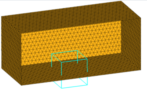 Figure 9. Boundary Region Selected as With BL (flat) and Remesh 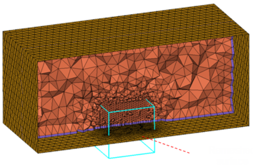 Figure 10. Remeshed Surface. The region included in the refinement box has been remeshed with the elements size assigned to the refinement box. |
| freehand edit | Open the morphing Freehand panel, from which you can alter the shape and dimensions of the refinement box to better suit your mesh. |
Tetramesh Panel Functions Subpanel
| Option | Action |
|---|---|
| float trias/quads | Match the node locations of the volume elements with those of the surface mesh, but the connectivity may be modified to produce a better mesh. Normally, this results in some tetra faces going across tria diagonals. Base quad surface elements are split into two trias |
| fixed trias/quads | Match the node locations of the volume elements with those of the surface mesh. It guarantees the connectivity of the tetras with the trias. Use this option whenever you need to match other components to the resulting volume mesh, or when you need to generate layers composed of pentas/hexas. |
| fix comp boundaries | If the float option is
chosen for some boundary regions, Engineering Solutions is
allowed to swap surface shell edges during mesh generation.
However, this prevents the swapping of edges between two
components.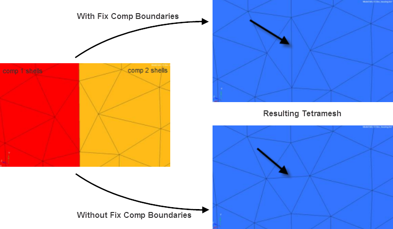 Figure 11. |
| update input shells | Automatically update the shells on boundaries without boundary layers after the meshing step, and organize the updated shell elements in the initial boundary shell components. |
| Quad transition mode: split quads / smooth pyramid / simple pyramid | Select how the mesher
creates a transition from quadrilateral surface elements to
internal tetrahedral elements.
|
| fixed with boundary layer | Select tria/quad
elements that define the surface from which boundary layer
elements are generated. Note: Available in the CFD mesh
subpanel.
|
| float w/o boundary layer | Select tria/quad
elements on surfaces that do not require boundary layer elements
(for example far-field, inlet, outlet, symmetry
planes). Note: Available in the CFD mesh
subpanel.
|
| Total BL thickness / ratio of total thickness to element size / number of layers | Choose a method for
defining the thickness of the boundary layer(s).
Note: Available in the CFD mesh subpanel.
|
| structured isotropic prisms | Use the local element
size for the initial thickness and a value of 1.0 for the growth
rate and acceleration. You can use structured isotropic prism
layers in any situation where ordered layers of tetras are
required near the surface. The mesher uses as many layers of
isotropic elements as possible until the elements in the next
layer are of unacceptable quality, and then it switches to the
normal meshing algorithm. Note: Available in the CFD mesh
subpanel's native BL option.
|
| exponential boundary layer | Use the first layer
thickness, growth rate, and acceleration parameters to generate
boundary layers up to a point where the thickness is of the same
order as the base surface element, and then generate the
remaining core with tetrahedral elements. Note: Available in the
CFD mesh subpanel's native BL option.
|
| tetra mesh normally / optimize meshing speed / optimize meshing quality | Choose a meshing
optimization method.
|
| Growth options | Select a growth option
to control the tradeoff between the number of elements generated
and the element quality.
|
| uniform layers |
Select how far the constant tetra size should be maintained from the surface mesh during tetrameshing. The distance is internally calculated by multiplying the user defined factor by the local surface mesh size.Engineering Solutions specifies different default value of this parameter.
|
| growth rate |
If d is the initial thickness and r is the initial growth rate, then the thicknesses of the successive layers are d, d*r, d*r^2, d*r^3, d*r^4, and so on. If element quality is very important and you are not concerned with the total number of elements created, then Interpolate will produce the best results because the element size changes smoothly and therefore the element quality is better. Engineering Solutions specifies different default value of this parameter.
Note: Available when the growth method is set to user
controlled.
|
| initial layers | Specify a boundary
region of d times the local surface element size where tetras
should be of constant size. This value can be interpreted as the
number of initial layers of tetrahedral elements generated
without size correction by growth rate. Note: Available when the
growth method is set to user controlled.
|
Command Buttons
| Button | Action |
|---|---|
| mesh | Generate the mesh. |
| reject | Undo the creation of the mesh, discarding all related elements. |
| mesh to file | Store the generated mesh in a .fem file after meshing is finished. When enabled, specify a location to export the mesh. |
| check 2D mesh | Validate the input surface mesh before performing volume mesh generation using the Boundary Shell Checker tool. |
| fix 3D elements | Fix 3D elements in the
following ways using the Solid Mesh Optimization tool.
|
| return | Apply all changes and close the panel. |