/MAT/LAW58 (FABR_A)
Block Format Keyword This law describes a hyperelastic anisotropic fabric material. It uses an anisotropic coordinate system with anisotropy angle, following element deformation.
The material formulation provides coupling between warp and weft directions in order to reproduce physical interaction between fibers. The shear degree of freedom is fully decoupled from the translational degrees of freedom. Optionally, nonlinear stress-strain curves for loading and unloading can be specified for warp, weft directions and in shear.
Format
| (1) | (2) | (3) | (4) | (5) | (6) | (7) | (8) | (9) | (10) |
|---|---|---|---|---|---|---|---|---|---|
| /MAT/LAW58/mat_ID/unit_ID or /MAT/FABR_A/mat_ID/unit_ID | |||||||||
| mat_title | |||||||||
| E1 | B1 | E2 | B2 | Flex | |||||
| G0 | GT | Gsh | sens_ID | ||||||
| Df | Ds | Gfrot | ZeroStress | ||||||
| N1 | N2 | S1 | S2 | Flex1 | Flex2 | ||||
| (1) | (2) | (3) | (4) | (5) | (6) | (7) | (8) | (9) | (10) |
|---|---|---|---|---|---|---|---|---|---|
| fct_ID1 | Fscale1 | ||||||||
| fct_ID2 | Fscale2 | ||||||||
| fct_ID3 | Fscale3 | ||||||||
| fct_ID4 | fct_ID5 | Fscale4 | Fscale5 | fct_ID6 | Fscale6 | ||||
Definitions
| Field | Contents | SI Unit Example |
|---|---|---|
| mat_ID | Material
identifier (Integer, maximum 10 digits) |
|
| unit_ID | Unit Identifier (Integer, maximum 10 digits) |
|
| mat_title | Material
title (Character, maximum 100 characters) |
|
| Initial
density (Real) |
||
| E1 | Young's modulus in
the warp direction. (Real) |
|
| B1 | Softening
coefficient in the warp direction. Default = 0.00 (Real) |
|
| E2 | Young's modulus in
the weft direction. (Real) |
|
| B2 | Softening
coefficient in the weft direction. Default = 0.00 (Real) |
|
| Flex | Fiber bending
modulus reduction factor. Default = 0.01 (Real) |
|
| G0 | Initial shear
modulus. Default = G, where (Real) |
|
| GT | Tangent shear
modulus at
. (Real) |
|
| Shear locking
angle. (Real) |
||
| Gsh | Traverse shear
modulus (only used with multi-layer property). Default (Real) If G0 = 0, then |
|
| sens_ID | Sensor identifier
to activate reference geometry. 8 (Integer, maximum 10 digits) |
|
| Df | Damping coefficient
in the warp and weft directions (0.0 <
Df
< 1.0). 2 Default = 0.00 (Real) |
|
| Ds | Friction
coefficient between fibers in shear (0.0 <
Ds
< 1.0). 6 Default = 0.00 (Real) |
|
| Gfrot | Shear friction
modulus. 6 Default (Real) If G0 = 0, then |
|
| ZeroStress | Zero stress flag
for initial stresses in tension and compression by using
reference state geometry. 7
(Real) |
|
| N1 | Fiber density
(number of fiber per length unit) in warp direction. 1 Default = 1 (Integer) |
|
| N2 | Fiber density
(number of fiber per length unit) in weft direction. 1 Default = 1 (Integer) |
|
| S1 | Straightening
strain in the warp direction. 5 Default = 0.10 (Real) |
|
| S2 | Straightening
strain in the weft direction. 5 Default = 0.10 (Real) |
|
| Flex1 | Fiber bending
modulus reduction factor in warp direction. 5 Default = Flex (Real) |
|
| Flex2 | Fiber bending
modulus reduction factor in weft direction. 5 Default = Flex (Real) |
|
| fct_ID1 | Loading function identifier for
true stress vs true strain in warp direction. 3 Default = 0 (Integer) |
|
| Fscale1 | Scale factor for ordinate of
function 1. Default = 1.0 (Real) |
|
| fct_ID2 | Loading function identifier for
true stress vs true strain in weft direction. 3 Default = 0 (Integer) |
|
| Fscale2 | Scale factor for ordinate of
function 2. Default = 1.0 (Real) |
|
| fct_ID3 | Loading function identifier for
true shear stress vs the anisotropy complementary angle (in
degrees) between fiber directions (axes of anisotropy).
6 Default = 0 (Integer) |
|
| Fscale3 | Scale factor for ordinate of
function 3. Default = 1.0 (Real) |
|
| fct_ID4 | Loading function identifier for
unloading for true stress vs true strain in warp direction.
3 Default = 0 (Integer) |
|
| Fscale4 | Scale factor for ordinate of
function 4. Default = 1.0 (Real) |
|
| fct_ID55 | Unloading function identifier
for unloading for true stress vs true strain in weft
direction. 3 Default = 0 (Integer) |
|
| Fscale5 | Scale factor for ordinate of
function 5. Default = 1.0 (Real) |
|
| fct_ID6 | Unloading function identifier
for true shear stress vs the anisotropy complementary angle
(in degrees) between fiber directions (axes of anisotropy).
6 Default = 0 (Integer) |
|
| Fscale6 | Scale factor for ordinate of
function 6. Default = 1.0 (Real) |
Example (Fabric with parameter input)
#RADIOSS STARTER
#---1----|----2----|----3----|----4----|----5----|----6----|----7----|----8----|----9----|---10----|
/UNIT/1
unit for mat
                  kg                   m                   s
#---1----|----2----|----3----|----4----|----5----|----6----|----7----|----8----|----9----|---10----|
#-  2. MATERIALS:
#---1----|----2----|----3----|----4----|----5----|----6----|----7----|----8----|----9----|---10----|
/MAT/LAW58/1/1
FABRIC
#              RHO_I
               722.5
#                 E1                  B1                  E2                  B2                FLEX
           450000000                   0           450000000                   0                0.01
#                 G0                  GT              AlphaT                 Gsh           sensor_ID
                   0            10000000                  60                   0                   0
#                 Df                  Ds               GFROT                             ZERO_STRESS
                 .05                 .05                   0                                       0
#       N1        N2                  S1                  S2               FLEX1               FLEX2
         1         1                 .05                 .05                   0                   0
#---1----|----2----|----3----|----4----|----5----|----6----|----7----|----8----|----9----|---10----|
#ENDDATA
/END
#---1----|----2----|----3----|----4----|----5----|----6----|----7----|----8----|----9----|---10----|
Example (Fabric with function input)
#RADIOSS STARTER
#---1----|----2----|----3----|----4----|----5----|----6----|----7----|----8----|----9----|---10----|
/UNIT/1
unit for mat
                  kg                  mm                  ms
#---1----|----2----|----3----|----4----|----5----|----6----|----7----|----8----|----9----|---10----|
#-  2. MATERIALS:
#---1----|----2----|----3----|----4----|----5----|----6----|----7----|----8----|----9----|---10----|
/MAT/LAW58/1/1
Altair test fabric LAW58
#              RHO_I
               8e-07
#                 E1                  B1                  E2                  B2                FLEX
                0.38                   0                0.38                   0                   1
#                 G0                  GT              AlphaT                 Gsh           sensor_ID
              0.0035              0.0055               7.175                   0                   1
#                 Df                  Ds               GFROT                             ZERO_STRESS
                0.00                0.00                   0                                       1
#       N1        N2                  S1                  S2               FLEX1               FLEX2
         1         1                   0                   0                   0                   0
#  fct_ID1                       Fscale1
       500                             1
#  fct_ID2                       Fscale2
       501                          1.07
#  fct_ID3                       Fscale3
       502                             1
#---1----|----2----|----3----|----4----|----5----|----6----|----7----|----8----|----9----|---10----|
/FUNCT/500
stress-strain curve dir 1
#        true strain         true stress
   0.0000000000e+000                   0
   9.9503308532e-003   2.9636979188e-003
   1.9802627296e-002   5.3682944250e-003
   2.9558802242e-002   7.1312474875e-003
   3.9220713153e-002   8.7543744167e-003
   4.8790164169e-002   1.0626227281e-002
   5.8268908124e-002   1.2828957400e-002
   6.7658648474e-002   1.5214981140e-002
   7.6961041136e-002   1.7923677525e-002
   8.6177696241e-002   2.0931047458e-002
   9.5310179804e-002   2.4244941875e-002
   1.0436001532e-001   2.8050134750e-002
   1.1332868531e-001   3.2157106333e-002
   1.2221763272e-001   3.6791281562e-002
   1.3102826241e-001   4.1811352500e-002
   1.3976194238e-001   4.7185817708e-002
   1.4842000512e-001   5.3009665500e-002
/FUNCT/501
stress-strain curve dir 2
#        true strain         true stress
   0.0000000000e+000                   0
   9.9503308532e-003   3.7850414917e-003
   1.9802627296e-002   6.6041801875e-003
   2.9558802242e-002   8.9026150938e-003
   3.9220713153e-002   1.1200598067e-002
   4.8790164169e-002   1.3569178437e-002
   5.8268908124e-002   1.6244941225e-002
   6.7658648474e-002   1.9356706823e-002
   7.6961041136e-002   2.2930409250e-002
   8.6177696241e-002   2.7109342313e-002
   9.5310179804e-002   3.1773431250e-002
   1.0436001532e-001   3.6903321313e-002
   1.1332868531e-001   4.2590270333e-002
   1.2221763272e-001   4.8734555250e-002
   1.3102826241e-001   5.5311888000e-002
   1.3976194238e-001   6.2350489167e-002
   1.4842000512e-001   6.9690045000e-002
#---1----|----2----|----3----|----4----|----5----|----6----|----7----|----8----|----9----|---10----|
/FUNCT/502
stress-strain curve dir 12
#              angle         true stress
  -16.170000000e-000  -1.5741500000e-003
  -7.1750000000e-000  -4.3750000000e-004
   0.0000000000e+000   0.0000000000e+000
   7.1750000000e-000   4.3750000000e-004
   16.170000000e-000   1.5741500000e-003
#ENDDATA
/END
#---1----|----2----|----3----|----4----|----5----|----6----|----7----|----8----|----9----|---10----|
Comments
- This law is used with the properties, /PROP/TYPE16 (SH_FABR), /PROP/TYPE19 (PLY), /PROP/TYPE51, /PLY and /PROP/PCOMPP.
- Fiber
characterization:
- N1 and N2 are the number of fibers per length unit, which are used to calculate stress in both fiber directions.
- The fiber directions (warp and weft) define local axes of anisotropy. Material data is specified independently for each direction and in shear.
- Fiber damping is used to suppress instabilities as a result of elastic material behavior. The recommended value for the damping coefficient in the fiber direction Df is 0.05.
- Rules concerning input
functions for the optional loading and unloading stress-strain curves.
- All tabulated input curves must be monotonically increasing. Radioss Starter will output write an error message when the input is not monotonically increasingin case of wrong input.
- Case without unloading (fct_ID4=fct_ID5=fct_ID6=0):
All loading functions are optional. The user may use an analytical formula or define a loading function in any direction. Tabulated and analytical behavior may be mixed in any direction.
- Case of loading / unloading with hysteresis with at least one
unloading function is defined.
- Loading functions tabulated input in are loading is mandatory in all directions. Functions fct_ID1, fct_ID2, and fct_ID3 must all be defined. It is not possible to mix analytical formulae in loading with unloading functions.
- Not all unloading curves need to be defined. If an unloading curve is missing in any direction, the loading and unloading will take the same path with no hysteresis.
- If loading and unloading functions are defined, they must have strictlyonly one intersection point to define the hysteresis loop. An error message is written in case on incorrect input. The exception is the shear functions are curves in shear which must have two intersection points for negative and positive values.
- An error message is written when input is incorrect.
- Stress-strain
relation in tension and compression in direction of fibres.
- When nonlinear functions are used.fct_ID1, fct_ID2 define loading and fct_ID4, fct_ID5 unloading behavior
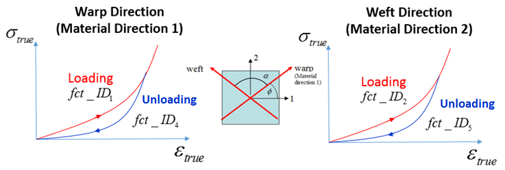
Figure 1. - When parameters are used, the analytical relationships between
stress and strain are defined as:
- For Loading
(1) - For Unloading
(2)
The analytical parameters are not used if the nonlinear functions (fct_ID1, fct_ID2, fct_ID4 and fct_ID5) are specified. However, the values E1, E2, are still required to calculate the prestress from the reference geometry and evaluate material stiffness used in contact. In such cases, E1, E2 should correspond to average stiffness (average slope) of the corresponding loading functions.
- For Loading
- When nonlinear functions are used.
- Initial straightening
effect of the woven fabric.This material allows you to account for the initial straightening effect of the woven fabric.
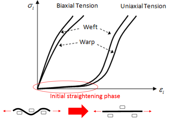
Figure 2.- It is assumed to be softer in the tensile direction during
the straightening phase. In biaxial tension there is no
straightening phase and the fibers bear loads from the
beginning of the loading phase.
Use factor Flexi to scale the E modulus or function (fct_ID1 or fct_ID2) in corresponding direction.
(function input)
(parameter input)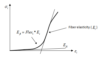
Figure 3.- If the value of Flex1 or Flex2 is equal to zero, then the value of Flex will be used.
- The straightening portion of the strain is given by the strains S1 and S2 for direction 1 and 2 correspondingly.
- The functions fct_ID1 and fct_ID2 correspond to biaxial tension, where the initial straightening is not taken into account. In uniaxial tension, the straightening effect is accounted for by using Flex1 and Flex2 in the stress calculation. It is similar to the case when E1 and E2 are specified instead of the curves.
- In compression, the Young's modulus is always:
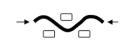
Figure 4.
- It is assumed to be softer in the tensile direction during
the straightening phase. In biaxial tension there is no
straightening phase and the fibers bear loads from the
beginning of the loading phase.
- Stress-strain
relation in shear.
- When tabulated input is present fct_ID3 is used for loading and fct_ID6 for unloading.
- If fct_ID6 is not specified, the material is assumed to be hyperelastic, and the loading and unloading paths are the same.
- If fct_ID6 is given, the material shows hysteresis behavior with different path for loading and unloading in shear directions.
- The nonlinear functions (fct_ID3, fct_ID6) are not mandatory. If these functions are not specified, the corresponding values of G0, and GT are used to calculate the stress-strain relationship of the material.
- For function fct_ID3, fct_ID6, which determine loading and unloading in shear the abscissa should be set in degrees. The functions should be specified both for negative and positive values of the angle (normally the functions are symmetrical).
- Absolute value of the angle, and its value should be less than 90 degrees, .
- Loading and unloading functions should pass through
point (0,0). Loading and unloading curves should have
exactly one intersection point for negative angle and
another intersection point for positive angle.
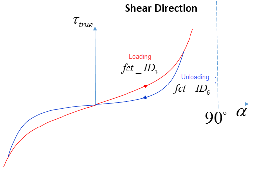
Figure 5.The anisotropy complementary angle which is equal to the difference between 90 degrees and the current angle between the anisotropy axes.
- When parameters are used to describe relation between shear stress
and angle, two different shear situations could be described:
- In plane (1 - 2) shear:Before shear locking angle :
(3) After shear locking angle :(4) 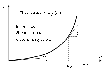
Figure 6.Where,- Shear locking angle
- GT
- Shear modulus at
- G0
- Shear modulus at
- If the G0 = 0, then its value is calculated to avoid discontinuity of the shear modulus at : G0 = G
- The values of G0 and GT are ignored if the nonlinear functions (fct_ID3 and fct_ID6) are specified. However, the values G0 is still required to calculate the prestress from the reference geometry and evaluate material stiffness used in contact. In such cases, G0 should correspond to average stiffness (average slope) of the corresponding loading functions.
-
is an initial
complementary angle, which is equal to the difference
between 90 degrees and the initial angle between the
anisotropy axes defined in the shell property (/PROP/TYPE16 (SH_FABR)). Note: Initial pre-stress exists in the fabric material if initial angle between the fiber axes specified in the property is not equal to 90 degrees.
- It is also possible to describe interaction shear stress between fibers. Use Gfrot (the shear modulus) to calculate interaction shear stress ( ) between fibers. The friction in-plane shear stress between the fibers is calculated as .
- Out-of-plane shear:
It is possible to describe transverse shear between multi-layers (plies) with shear modulus .
- In plane (1 - 2) shear:
- When tabulated input is present fct_ID3 is used for loading and fct_ID6 for unloading.
- The ZeroStress flag is used to remove initial stresses in the folded airbag. These initial stresses arise during the folding process. Numerically this pre-stress is specified through a reference airbag geometry which represents an unfolded airbag state. If ZeroStress=1, then compressive and tensile initial stresses are set to zero and then gradually increase to the actual value after deployment begins.
- sens_ID is used only with ZeroStress =1 and reference airbag geometry. It activates the pre-stress based on the values output from the sensor. This is useful for airbags with time to fire > 0.
- Output for
post-processing:This material uses the anisotropic coordinate system, with the angle between the material coordinate system axes (anisotropy angle) updated based on the element deformation. Special user-defined output should be used to evaluate stresses, strains, and the shear angle alpha. In the /TH/SHEL and /TH/SH3N entries in the Starter file and in /H3D/SHELL or /ANIM/SHELL in the Engine file, you should specify the following:
- /H3D/SHELL/USER/UVAR=1 or /ANIM/SHELL/USR1 - stress in fiber direction 1
- /H3D/SHELL/USER/UVAR=2 or /ANIM/SHELL/USR2 - stress in fiber direction 2
- /H3D/SHELL/USER/UVAR=3 or /ANIM/SHELL/USR3 - stress in shear direction
- /H3D/SHELL/USER/UVAR=4 or /ANIM/SHELL/USR4 - strain in fiber direction 1
- /H3D/SHELL/USER/UVAR=5 or /ANIM/SHELL/USR5 - strain in fiber direction 2
- /H3D/SHELL/USER/UVAR=6 or /ANIM/SHELL/USR6 - tan(α)
- /H3D/SHELL/ALPHA - Shear angle alpha of material /MAT/LAW58 in degrees.
Due to special material formulation (decoupled DOF with special interaction between fibers), the stress component does not form a stress tensor; therefore, usual tensor evaluations such as von Mises stress, principal stresses, and so on, have no meaning for the material.