When creating mesh-dependent realizations with quad transitions, the quad transition
meshes can overlap and disturb each other if more than one set of connectors is created too
close to each other. The Connector Imprint panel enables you to reconcile such transitions
with each other and then modify the underlying mesh to match the results, creating a
seamless, properly meshed final result.
Location: Connectors module
Use of the Mesh Edit panel is generally only required when sets of connectors with quad
transitions are located too close to each other for the specified mesh size.
Panel Options
Option
Action
source
Select elements to be imprinted into the destination mesh
when the imprint is performed.
destination
Select the elements which are intended to assimilate the
imprint mesh.
elems to destination comp
Organize imprint elements into the appropriate components of
the destination mesh. Clear this checkbox to keep imprint
elements in their origin component. Figure 1.
create
Apply the imprint based on the provided input.
reject
Reverse the last imprint action.
Note: The imprint is
finalized if you leave the panel, so that you cannot reject
it if you leave the panel and then return
again.
return
Exit the panel. Save the current state of the imprint, but do
not save the panel settings.
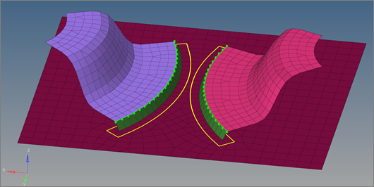
In Figure 2, the
regular quad mesh can be easily performed. There is enough space available and the
quad transition areas don't conflict each other. Figure 2.
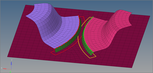
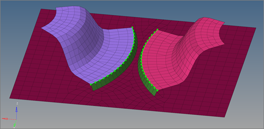
However, when the components are brought closer together, the realization is
disturbed because the transition areas conflict with each other.
Smaller conflicts are resolved automatically when realizing the connectors. This
releases the overlapping elements and performs a normal remesh in that area. This is
permitted as long as the overlapping area is smaller than half the regular quad
transition element size. Figure 3.
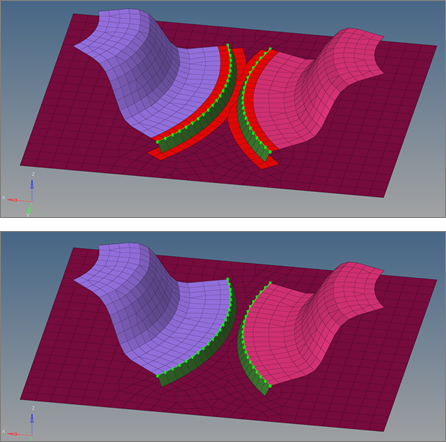
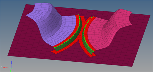
However, if a conflict is too great it cannot be resolved in this fashion. For such
cases, the Mesh Edit panel's functionality can be used to solve the problem. Figure 4.
Ideally all connectors expected to conflict with each other are realized with the
skip imprint option in a first step. This creates the weld elements and the mesh
pattern for each connector. The pattern elements are organized into a component
named ^conn_imprint. Figure 5.
In the second step, the conflicting elements can be manually modified with all of the
functions that Engineering Solutions provides.
Note: To ensure that
the seam elements are completely attached to the underlying mesh after
performing the mesh imprint, each element edge at the foot needs to be attached
to at least one imprint element. The nodes at the seam foot have to stay
untouched; otherwise the connector becomes unrealized.
Figure 6.
In a third step the manual mesh imprint is performed. The elements from the
^conn_imprint component are selected as the source and the elements from the
affected components are selected as destination mesh.
Note: The mesh edit
- imprint functionality can be used in various situations, but when using it
together with connectors certain rules should be taken into account. The imprint
mesh (source) should not cross the borders of the destination mesh or component,
whether at a free edge or at a changeover to another component. Furthermore, the
imprint mesh should not exceed a certain distance from the destination mesh. You
can limit this by enabling the check max distance checkbox. Only when these
requirements are met can reliable results can be expected.
Figure 7.
By enabling the elems to destination comp checkbox, the elements from the
^conn_imprint components are automatically organized into the appropriate
destination components. Figure 8.