Node Edit Panel
Use the Node Edit panel to associate nodes to a point, line, or surface/solid face; move nodes along a surface; place a node at a point on a surface; remap a list of nodes to a line; or project nodes to an imaginary line passing through two nodes.
Location: Geom page
Settings are preserved if you switch between subpanels, but selections of nodes, surfaces, and so on are not.
Associate Subpanel
Use the Associate subpanel to create an association between the selected nodes and a selected piece of geometry. Nodes are projected to the geometry, provided the distance to the selected geometry is within the search tolerance. The tolerance is used to create a search sphere at each of the selected nodes. If the selected geometry is found within that search sphere, the node is projected to the closest point on the geometry. An association is made within the database between the nodes (and corresponding elements) and geometry, so any subsequent selection routines can reference either entity. For example, if creating a boundary condition (such as a force, pressure, or constraint) on the geometry, the boundary condition will be applied to the nodes and or elements upon export.
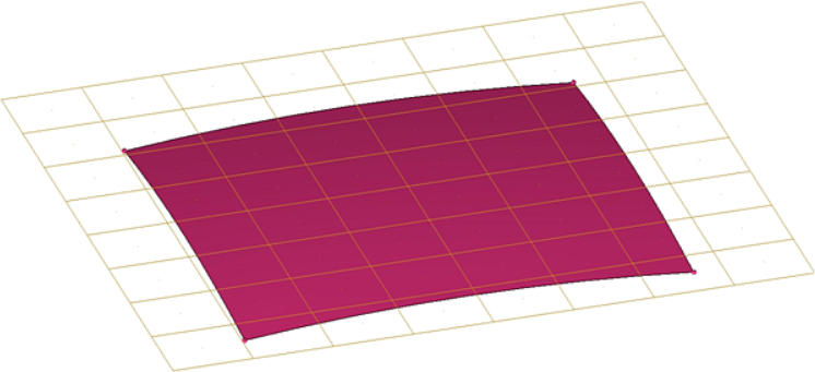
Figure 1.
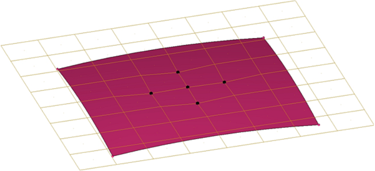
Figure 2.
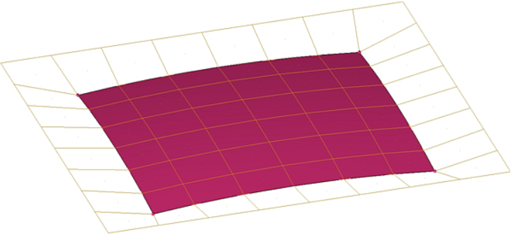
Figure 3.
| Option | Action |
|---|---|
| geometry selector | Select the geometry to which the nodes will be associated. |
| nodes | Select the desired nodes. |
| tolerance | Nodes farther from the point/line/surf/solid than this value will not become associated to it. This allows you to perform a quick mass-node selection (such as when using window selection) without actually associating nodes that should not be associated to the chosen geometry. |
Move Node Subpanel
| Option | Action |
|---|---|
| nodes | Select the desired nodes. |
| plane and vector selector | Specify the direction for the node(s) to move, either by defining an axis, vector, or a plane (in which case the noes will move in the plane's positive normal direction as determined via the right-hand rule). |
| step size | Specify the distance that the selected nodes will travel in the specified direction each time move+ or move- are clicked. |
Place Node Subpanel
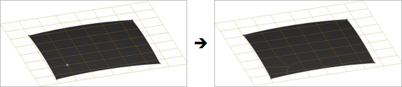
Figure 4.
| Option | Action |
|---|---|
| destination surf | Select the surface onto which you wish to place the node. |
| node to place | Select the desired node, then click the desired location on the selected surface. The node relocates automatically. |
Remap Subpanel
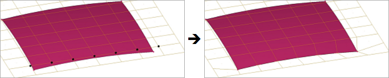
Figure 5. Selected Nodes Mapped to the Surface Edge. Selected nodes become evenly distributed across the surface edge.
| Option | Action |
|---|---|
| node list | Select the series of nodes that you wish to remap. |
| line list | Select the line(s) to which you wish the node list to relocate. |
Align Node Subpanel
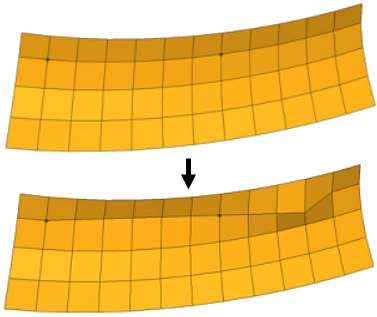
Figure 6. Align Nodes. The first image shows the two selected nodes that define an infinite line. The second image shows that any nodes selected will be projected to that line.
| Option | Action |
|---|---|
| 1st end: node | Select a node that defines one end of the imaginary line. |
| 2nd end: node | Select a node that
defines the other end of the imaginary line. Once both nodes are selected, you are prompted to pick the nodes that you wish to align. |
| nodes/node | Choose whether to
select one or more nodes. When set to nodes, click align after you are finished selecting nodes. |
| use ratio | Specify a ratio to
align nodes. Note: Available when aligning one node at a
time.
|
Command Buttons
| Option | Action |
|---|---|
| associate | Associate the selected nodes with the selected geometric entity. |
| reject | Undo the most recent node edit. |
| move+ | Move the nodes in the direction specified by the specified step size. |
| move- | Move the nodes opposite to the direction specified by the specified step size. |
| remap | Relocate nodes to a selected line list. |
| return | Exit the panel, finalizing any edits made (you cannot reject an edit after leaving the panel, even if you return later.) |