Reflect Panel
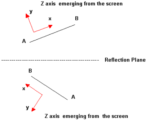
Use the Reflect panel to reflect portions of a model about a plane, changing the selected portion into a mirror image of itself.
Location: Tool page
Undo a reflection by clicking reflect again without changing any other settings.
Nodes located on the plane of reflection are not equivalenced. This function is available in the Edges panel.
Loads, constraints, and systems attached to the reflected structure move to the new location of the parent entity, but they are not reflected.
Local coordinate systems can be used to define the plane of reflection by using the vector option and selecting one of the vectors defining the local system.
Reflecting surfaces separately from the nodes or elements built on them breaks association with those nodes/elements. Reflecting surfaces back to their original position will not restore these associations, but they can be restored via the Node Edit panel.
When reflecting a component, all of the geometry (lines, surfaces, connectors, and points) and elements (nodes) contained in each component are reflected with the component, and associations are maintained.
Panel Options
| Option | Action |
|---|---|
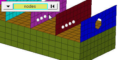
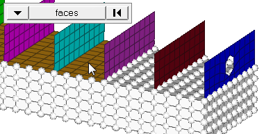
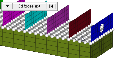
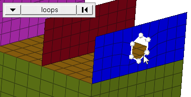
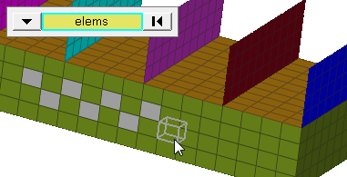
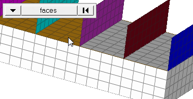
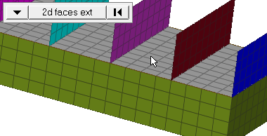
| entity selector | Select entities for
reflection. When you select nodes or elems, click the switch
to change the selection mode.
|
| plane selector | Define the plane of
reflection.
|
| Bar Elements | Choose a method for
reflecting bar elements.
Note: Available when selecting elements or components using the
entity selector.
|
| face angle / individual selection |
|
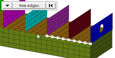
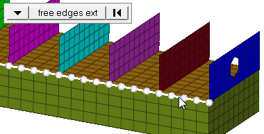
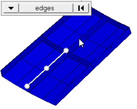
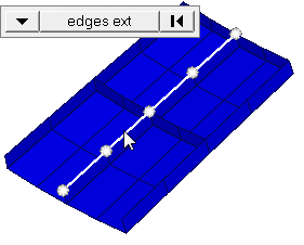
| edge angle |
Split edges that belong to a given face. When the edge
angle is 180 degrees, edges are the continuous boundaries of faces. For smaller
values, these same boundary edges are split wherever the angle between segments
exceeds the specified value. A segment is the edge of a single element.
Important: Only available when the entity selector is set to nodes and the
selection mode is set to free edges, free edges ext, edges, or edges
ext.
|
Command Buttons
| Button | Action |
|---|---|
| reflect | Move the selected entities about the plane of reflection. |
| return | Exit the panel. |