Mesh Edit Panel
Use the Mesh Edit panel to extend a mesh to meet another mesh and form a good connection between them, or to imprint overlapping meshes so that they match one another.
The Mesh Edit panel consists of two subpanels, one for extending mesh and another for imprinting mesh. The functions you perform in one panel will not be carried over to the other panel. If you switch between the Imprint and Extend panels while working, you will not lose any of your work.
Imprint Subpanel
Use the Imprint subpanel to sync or line up meshes from different, overlapping components to facilitate a better modeling connection between them.
For example, mesh imprinting may be used to match up brackets that hold parts together, or to match up two different parts (components) that must be fastened to one another. By lining up the meshes of separate components on a node-by-node basis, connections such as welds, adhesives, or even bolts can be accurately modeled.
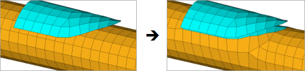
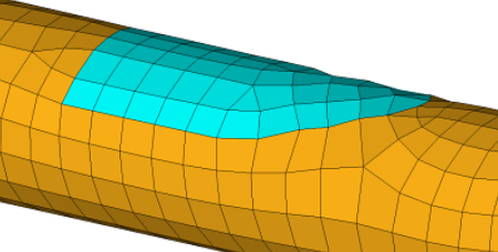
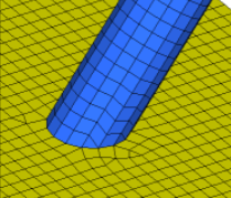
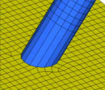
Figure 1. . The underlying tube is remeshed to match the plate, while retaining the mesh of both components.
| Option | Action |
|---|---|
| source | Choose between selecting elements, components, or nodes. In either case, this mesh will be considered the "source" for all further considerations, such as the projection path or which mesh remains after the imprint. |
| destination | Choose between selecting elements or components. In either case, this mesh will be considered the "destination" for the source mesh. |
| projection | Select the direction
that the source mesh is projected.
|
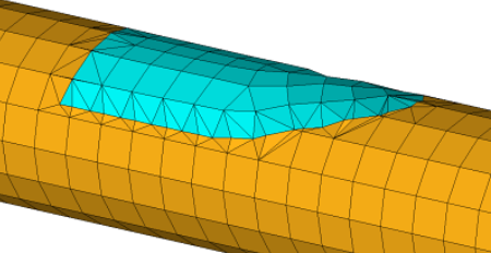
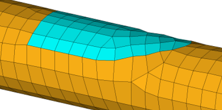
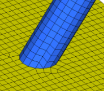
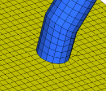
| remain | Select which of the
original meshes to retain. In Figure 2, Figure 3, and Figure 4 the blue plate is the source, while the
orange tube is the destination.
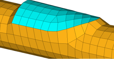 Figure 2. Using remain: source 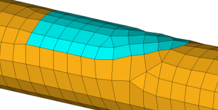 Figure 3. Using remain: destination 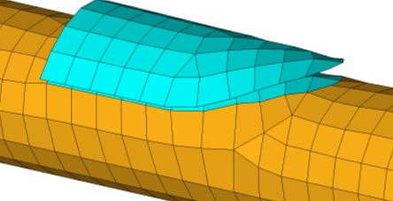 Figure 4. Using remain: both. Notice there are two layers of blue mesh now. The original component mesh and the destination imprint. |
| max distance | Fail imprints if the distance between any portion of the source and destination exceeds the value that specify in the distance field. |
| elems to destination comp | Absorb the imprint
source elements into the destination component, discarding the
original component's mesh. It is similar to the remain:
destination option, except that the end result is the
modified mesh within the destination component only.
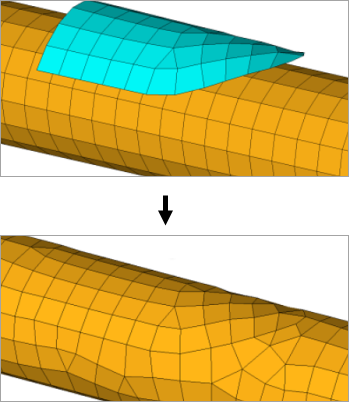 Figure 5. . The source mesh (blue, top) becomes part of the destination mesh (yellow). |
| create patch between imprints | Create a new patch
between the imprints. If nodes are selected in the source
selector, the new patch will be organized in the current
component by default. You can elect to have elements organized
in the destination component. Note: Available when remain is set
to both.
|
| remesh |
Choose how smoothly the imprint is made.
|
| feature angle | When the destination mesh contains an angle greater than this number of degrees, the imprint will not overlap that line in the destination. |
| settings: auto detect | Clear this checkbox to
specify an element type (quad, tria, mixed, R-trias, or quads
only) and element size to use during remesh. Note: Only available
when remesh is set to layers or all.
|
| anchor node | Select the nodes to be
inserted or fixed in the final destination mesh during mesh
imprinting when remeshing is performed.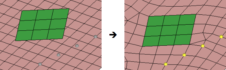 Figure 9. |
Extend Subpanel
Use the Extend subpanel to create smoothly-meshed connections between different components that do not quite touch, but are meant to. Meshes can be imprinted so that both components are remeshed to match, or so that the source component is remeshed to match the destination component, and vice-versa. You can also merge the elements of the source component into the destination component.
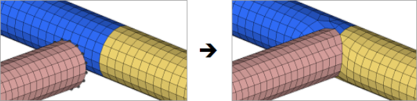
Figure 10. . One component (pink) is extended to join two others (blue and tan).
| Option | Action | ||
|---|---|---|---|
| source: nodes | Select the nodes along
the edge of the component to extend. Only the selected nodes
will be extended, therefore be certain to select all of the
nodes on the edge. Tip: From the extended entity
selection menu, select by path to
quickly select all of the nodes along the edge of the
component.
|
||
| destination: comps / elems | Choose between selecting elements or components. In either case, this mesh will be considered the "destination" for the source mesh to extend to. | ||
| projection: along tangent / normal to destination / along vector | Select the direction
to project the extension.
|
||
| feature angle: | When the destination
mesh contains an angle greater than this number of degrees, the
imprint will not overlap that line in the destination. This can lead to tapered extensions if the feature angles enclose a destination area that is narrower than the extension area. |
||
| remesh extension | Remesh the extended
mesh for better quality. Clear this checkbox to move the nodes
and not create new nodes or elements, which often results in
elongated elements.
|
||
| remesh destination: stitch only / layers / all | Define how to remesh
the target/destination mesh to accommodate the extended nodes'
positions.
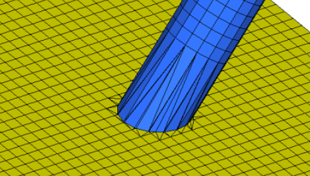 Figure 15. Stitch Only used on Destination 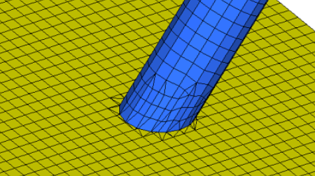 Figure 16. Stitch Only with Remesh Extension used on Destination 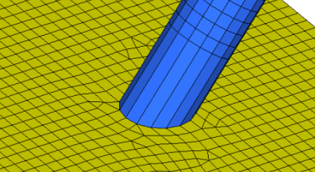 Figure 17. With Layers set to 5 Layers, but no Remesh used on Extension |
||
| settings: auto detect | Clear this checkbox to
specify an element type (quad, tria, mixed, R-trias, or quads
only) and element size to use during remesh. Note: Only available
when remesh destination is set to layers or
all.
|
||
| anchor node | Select the nodes to be
inserted or fixed in the final destination mesh during mesh
extension when remeshing is performed.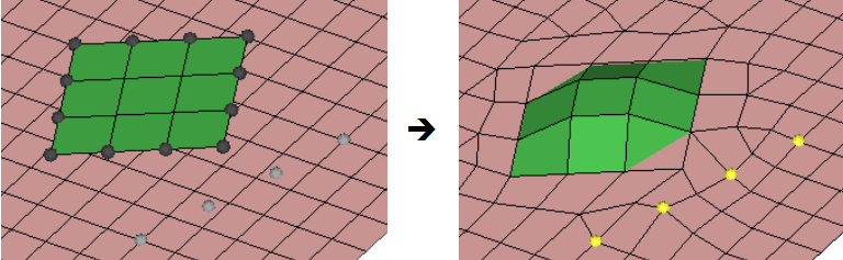 Figure 18. |
||
| create | Perform the extension using the specified settings. | ||
| reject | Reverse the last
extend action. Note: The extension is finalized if
you leave the panel, so you cannot reject it if you leave
the panel and then return again.
|
||
| return | Exit the panel. The current state of the extension is saved, but the individual settings are not. |
Command Buttons
| Button | Action |
|---|---|
| create | Perform the imprint or extension using the specified settings. |
| reject | Reverse the last
imprint or extension action. Note: The action is
finalized if you leave the panel, so you cannot reject it if
you leave the panel and then return again.
|
| return | Exit the panel. The current state of the imprint or extension is saved, but the individual settings are not. |