Spin Panel
Use the Spin panel to create a surface and/or mesh or elements by spinning a series of nodes, a line or lines, or a group of elements about a vector to create a circular structure.
Location: 2D and 3D pages
Spin Geoms Subpanel
Use the Spin Geoms subpanel to create a surface and/or mesh or elements by spinning a
series of nodes, a line, or lines about the normal of a user-defined plane.
| Option | Action |
|---|---|
| node list / lines selector | Select the nodes/lines to spin. |
| N1, N2, N3, B | Select a plane. The selected nodes are spun about the normal of the plane. |
| angle | Specify the angle through which to spin the nodes. |
| meshing options |
|
Spin Elems Subpanel
Use the Spin Elems subpanel to create a surface and/or mesh or elements by spinning a
group of elements about the normal of a user-defined plane.
| Option | Action |
|---|---|
| elems selector | Select the elements to spin. |
| N1, N2, N3, B | Select a plane. The elements are spun about the normal of the plane. |
| angle | Specify the angle through which to spin the elements. |
| on spin | Specify the number of elements to generate along the path of the spin. |
| bias style | Select a bias style. |
| bias intensity | Specify a bias intensity. |
Command Buttons
| Option | Action |
|---|---|
| spin + | Create the surfaces in the direction specified. |
| spin - | Create the surfaces in the opposite direction. |
| reject | Revert the most recent changes. |
| return | Exit the panel. |
Spin Nodes to Create a Surface
 Figure 1. Nodes Selected |
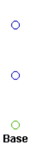 Figure 2. Base Node Selected |
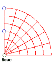 Figure 3. Surface Created |
Spin Lines to Create a Surface
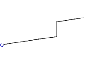 Figure 4. Nodes Selected |
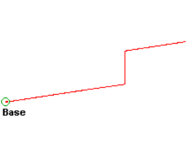 Figure 5. Base Point Selected |
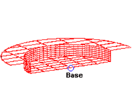 Figure 6. Surface Created |
Spin Elements to Create a Surface
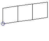 Figure 7. Elements Selected |
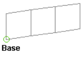 Figure 8. Base Point Selected |
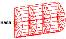 Figure 9. Surface Created |
Spin a Group of Elements to Create a Surface
|
Figure 10. Elements Selected |
Figure 11. Base Point Selected |
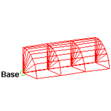 Figure 12. Elements Created using Spin+. The elements were created using spin +, with a negative biasing value. |
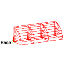 Figure 13. Elements Created without Element Biasing |