Vectors Panel
Use the Vectors panel to create a vector entity.
Location: 1D and Analysis pages
A vector represents a three dimensional direction.
In the modeling window, vectors are displayed as an arrow with the letters VEC and their vector size value at the tail end. By default, vectors are displayed using a representation of 100% of their actual length.
You can create several vectors at a time by selecting nodes and either a magnitude, or by deriving them from a line tangent or surface normal. Single vectors can be created by selecting two nodes or by deriving them from the cross product of two existing vectors.
Create Subpanel
Use the Create subpanel to create vectors.
Using base and magnitude, select one or more nodes at which to place vector entities. Specify the vectors by entering x, y and z components or by using the vector method. For the vector method, you must specify a magnitude and a direction. The direction is determined with a standard plane and vector selector by choosing two or three nodes (N1, N2, and N3), selecting a global axis, or selecting another vector. When using the N1, N2, and N3 option, two nodes define a vector along the selected nodes, while three nodes define a vector that is perpendicular to the plane defined by the selected nodes (using the right hand rule).
A vector can also be created by selecting two nodes using the two node vector creation method. No additional input is required in this case.
The cross product option derives a vector from two existing vector entities. The vector will be perpendicular to these vectors. The length can be entered or taken from either one of the selected vectors.
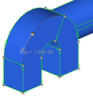 Figure 1. Vector Created on a Line |
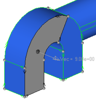 Figure 2. Vector Created on a Surface |
| Option | Action |
|---|---|
| vector creation method | Choose a method for
creating vectors.
|
| base node: nodes | Select all of the
nodes where you want a vector to be created.
Note: Available when the vector creation method is set to
base and magnitude.
|
| face angle / individual selection |
|
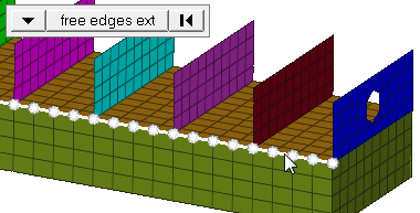
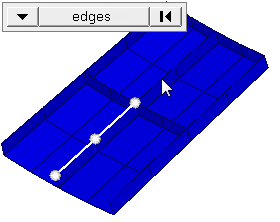
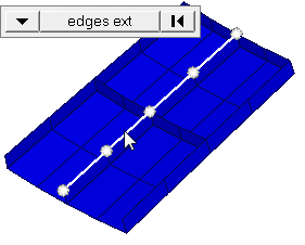
| edge angle |
Split edges that belong to a given face. When the edge
angle is 180 degrees, edges are the continuous boundaries of faces. For smaller
values, these same boundary edges are split wherever the angle between segments
exceeds the specified value. A segment is the edge of a single element.
Important: Only available when the entity selector is set to nodes and the
selection mode is set to free edges, free edges ext, edges, or edges
ext.
|
| from node / to node |
Create a vector by selecting two nodes.
Note: Available when
the vector creation method is set to two nodes.
|
| base node: node |
Select a node for the vector location. One vector can be
created at a time.
Note: Available when the vector creation method is set to cross
product.
|
| vector A: vector |
Select vector A.
Note: Available when the vector creation
method is set to cross product.
|
| vector B: vector |
Select vector B.
Note: Available when the vector creation
method is set to cross product.
|
| lines/surfaces |
Choose whether to derive vectors from lines or
surfaces.
Note: Available when the vector creation method is set to on
geometry.
|
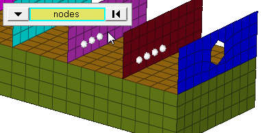
| nodes |
Select all of the nodes where a vectors needs to be
created.
Note: Available when the vector creation method is set to on
geometry.
|
| vector size % = / uniform size = |
Choose a method for changing the display size of vectors.
This setting does not affect the vector, only the length of its graphical
representation.
|
| label vector | Display labels for each of the vectors in the modeling window. |
| autoscale | Display vectors in relation to the model size. When enabled, the vector size fields are grayed out. |
| global system / local system |
Choose whether the vector is created either in the global or a local coordinate system. Example: You select three nodes N1, N2
and N3 which define a vector in the global z-direction (normal of the plane defined
by these three nodes). If the switch is set to local, the result will be a vector
pointing in the z-direction of the local system.
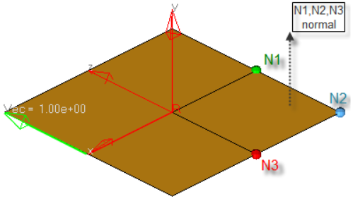 Figure 11. Note: Available when the vector creation method is set to base and
magnitude.
|
| vector / components |
|
| magnitude = / vector A / vector B |
Specify the length of a vector.
Note: Available when the vector creation method is set to cross
product.
|
| magnitude = / use parameterization |
If a vector is created on geometry, the length
can be entered directly or the parametric value can be used.
|
Update Subpanel
| Option | Action |
|---|---|
| vectors | Select the existing vectors to modify. |
| vector update method | Select a method for
update existing vectors.
|
| base node: nodes |
Select a node for the vector location. One vector can be
created at a time.
Note: Available when the vector creation method is set to cross
product.
|
| from node / to node |
Create a vector by selecting two nodes.
Note: Available when
the vector creation method is set to two nodes.
|
| base node: node |
Select a node for the vector location. One vector can be
created at a time.
Note: Available when the vector creation method is set to cross
product.
|
| vector A: vector |
Select vector A.
Note: Available when the vector creation
method is set to cross product.
|
| vector B: vector |
Select vector B.
Note: Available when the vector creation
method is set to cross product.
|
| lines/surfaces |
Choose whether to derive vectors from lines or
surfaces.
Note: Available when the vector creation method is set to on
geometry.
|
| nodes |
Select all of the nodes where a vectors needs to be
created.
Note: Available when the vector creation method is set to on
geometry.
|
| vector size % = / uniform size = |
Choose a method for changing the display size of vectors.
This setting does not affect the vector, only the length of its graphical
representation.
|
| label vector | Display labels for each of the vectors in the modeling window. |
| autoscale | Display vectors in relation to the model size. When enabled, the vector size fields are grayed out. |
| global system / local system |
Choose whether the vector is created either in the global or a local coordinate system. Example: You select three nodes N1, N2
and N3 which define a vector in the global z-direction (normal of the plane defined
by these three nodes). If the switch is set to local, the result will be a vector
pointing in the z-direction of the local system.
Figure 12. Note: Available when the vector creation method is set to base and
magnitude.
|
| vector / components |
|
| magnitude = / vector A / vector B |
Specify the length of a vector.
Note: Available when the vector creation method is set to cross
product.
|
| magnitude = / use parameterization |
If a vector is created on geometry, the length
can be entered directly or the parametric value can be used.
|
Command Buttons
| Button | Action |
|---|---|
| create | Create one or more new vectors based on the selected method. |
| reject | Revert the most recent create action. Does not display on the edit subpanel. |
| review | Click review, then click a vector to display the characteristics (for example creation method, magnitude) in the panel fields. |