What's New
View new features for Engineering Solutions 2021.
Aerospace 2021 Release Notes
New Features
- Aeroelasticity
- Dedicated ribbon for Aeroelasticity modelling tools is added for NastranMSC and OptiStruct user profiles in HyperWorks. It includes:
Altair Squeak and Rattle Director 2021 Release Notes
Overview
In this release, Squeak and Rattle Director (SnRD) is available within the HyperWorks suite. The SnRD Pre and Post-processing modules are available without the need for PSO installation.
The main focus areas are:
- Enhanced user experience
- Intuitive and highly automated engineering workflows
- Built-in industry best practices and engineering data
- Single platform for the designer, part-time analyst, and NVH-S&R CAE expert
The Squeak and Rattle analysis and investigation are available at every stage of the product development cycle, even when little or no data is available. This helps the analysts to drive the design changes by utilizing simulation, parallel to the design process.
New Features
- New SnRD Ribbon
- There is a new SnRD ribbon.
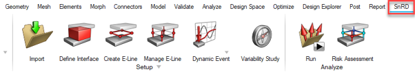
Figure 1. - It includes the following options and buttons:
- Setup
- Import model, configure files, create and manage evaluation lines, define loadcases, and setup variability studies.
- Analyze
- Export solver ready OptiStruct (.fem), model file (.hm), and HyperStudy template file for DoE and Stochastics run. Perform a quick risk assessment for the solved model containing evaluation lines.
- Risk Assessment
- Perform a quick assessment of squeak and rattle risks in the
model without switching to HyperView for post-processing on the
SnRD Post module.
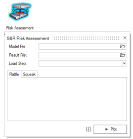
Figure 2. - SnRD Post
- Post process results to study and understand squeak and
rattle issues in the model using SnRD Post on HyperView. SnRD Post is now available
in HyperWorks.
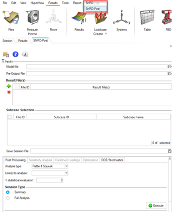
Figure 3.
- 2D Squeak Plot
- Plot the relative displacement in the contact plane for better squeak
evaluation. This plot is useful to fully understand the movement in the
contact plane and the principal directions.
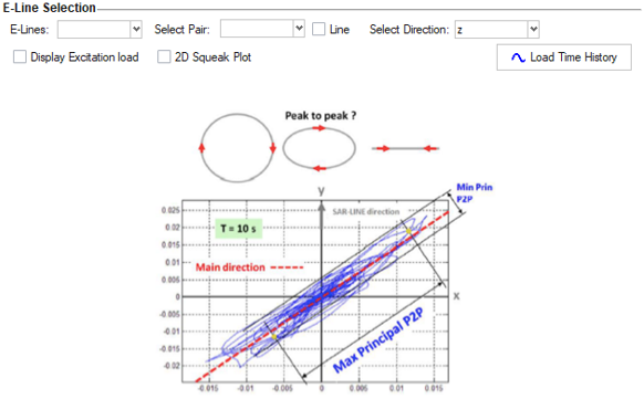
Figure 4. - Single Point E-Line using Element to Element Creation
- Create a single point E-line by selecting two elements. For example, create diagonal E-lines to track opening distortion, flexible attachments such as clips/snaps or other one point E-lines.
Enhancements
- Save Session
- Save and restore all progress made in SnRD in an .HM database.
- Define Interfaces
- Creation of geometrical lines can be controlled with advanced options,
such as combining and splitting.
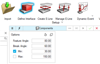
Figure 5. - Manage E-Lines
- Renumber E-lines through the E-line review table, one at a time or in
bulk by entering a range.
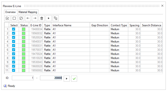
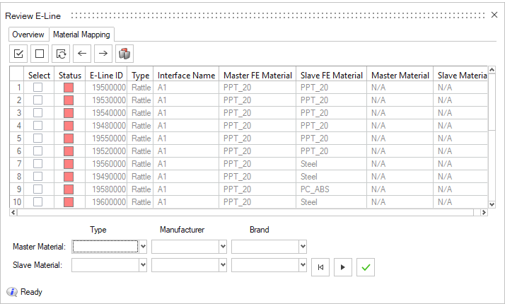
Figure 6. - Material Mapping via a separate tab in E-line review table. When
connected, all materials pairs in Ziegler database can also be
mapped.
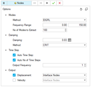
- Dynamic Event
- Control solver settings with advanced options in Dynamic Event
creation.
Known Issues
- Post-processing
-
- Due to a necessary check for improved stability, loading a result file in SnRD Post and Risk assessment takes longer in this version.
- Loading and comparing results from two load cases from two different result files with the same load case ID is not supported.
Resolved Issues
All issues reported in the previous versions are fixed in this version.
- E-line creation and realization performance, negatively impacted in the previous release, are now fixed.
- Numbering convention of E-lines is further improved and solved issues related to renumbering of E-lines.
Marine 2021 Release Notes
New Features
- Beam to Shell
- New feature to generate either surfaces or shell mesh equivalent to beam midmesh.
-
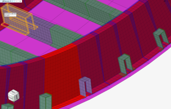
Figure 7. - Open Class 3D Exchange (OCX)
- This new version introduce support for OCX v2.8.5 xml schema as CAD import formats. OCX is intended to become an open industry standard for the exchange of design information between designer/yards and classification societies.
-
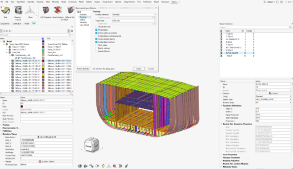
Figure 8.
Enhancements
- Exodus interface
- Marine tools such as Stiffener Meshing and CAD Properties have been extended to support Exodus solver profile.
Resolved Issues
- Foran CAD reader used to create old Assemblies instead of Parts/PartAssemblies. This issue has been fixed.
NVH Director 2021 Release Notes
New Features
- HyperWorks NVH
- A separate shortcut to invoke Hyperworks NVH. NVHD assembly building
features and functionalities are arranged in Assemble, Analyze, and
Tools ribbons. NVHD post-processing functionalities are arranged in Post
ribbon.
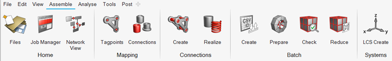
Figure 9. Assembly Ribbon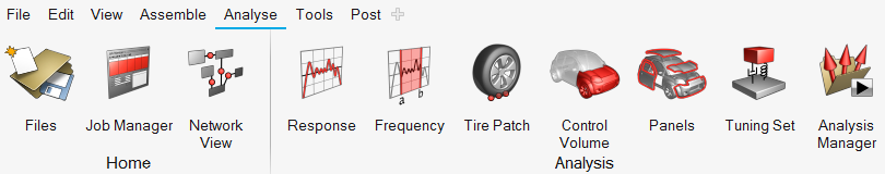
Figure 10. Analyze Ribbon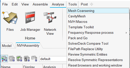
Figure 11. Tools Ribbon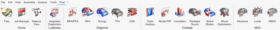
Figure 12. Post Ribbon - Analysis Manager with Multiple Configuration Support
- Analysis manager is redesigned to support multiple model configurations. Capability to create model configurations, analysis loadcase, and analysis setup in a modular way. An analysis can be created or batch runs can be submitted for possible valid combinations of model configuration, analysis loadcase, and analysis setup. Users can also review multiple analysis for quick comparison between different analysis.
- CAE Data Management and Versioning
- New feature for CAE Data Management and file-based versioning of Assembly XMLs and Representation files has been added, with the capability to version at multiple levels: team Vs analyst, major Vs minor. Access control with possibility to assign roles to users for editing and/or viewing. Effective management of tracking up-to-date files and file conflicts with clear traceability of individual and team changes allowing possibility of exchange data between different projects and/or previous versions.
- CDTire Support for Cavity
- Enhancement in the CDTire to support tire cavity and rolling effects and evaluate its performance on vehicle NVH responses.
- Modal Participation for ERP
- Enhancement in the Modal/Panel participation utility to support post-processing and diagnostics of modal participations for ERP.
Enhancements
- Network View
-
- Interaction between network view, assembly browser and graphics area
- Visualize Post-card image of module on hover over modules in network view
- Option to select configurations
- Option to realize/unrealize connections
- Option to get information on mass of modules and connections
- Option to prepare module
- Option of subsystem analysis
- Color palette for advanced connections
- Assembly XML Import Performance
- Significant performance improvement in the assembly XML import resulting from improvements in template import performance and saving HM file for that assembly instant.
- On-the-fly diagnostics computation for grid participation
- Enhancement in the integrated diagnostics to compute grid participation on-the-fly for road inputs and powertrain excitations. Display options and filters for diagnostics plots.
- Engine Mounts Optimization
- Enhancement in engine mount optimization to perform reliability-based optimization (RBDO) in addition to existing deterministic optimization.
Resolved Issues
- Issue related to identification of nodes in PreTest utility after animation of modes
- Issue related to DPR plot with legend showing between 0 to 1 only
- Issue related to saving of subxmls in Preserve mode where all subxmls were saving instead of only selected subxmls
- Issue related to rendering of configuration specific connections
Safety Tools
New Features
- Barrier Position Tool
- This new tool, available in the Safety ribbon in the LS-DYNA and Radioss
solver interfaces, enables an automatic positioning of the crash barrier
around the vehicle as per the selected safety regulation. The tool
provides following functionalities:
- Support of all safety regulations: C-NCAP, Euro-NCAP, FMVSS, IIHS, J-NCAP and UN-R
- Support of all load cases: Front, Side and Rear
- Following positioning methods are implemented: Overlapping method, Side with IRD method, Side with R-Point method, Pole
- User-defined gap between barrier and vehicle
- Automatic creation of transformations and positions entities
- Automatic switch of the barrier include file to *INCLUDE_TRANSFORM or /SUBMODEL respectively for LS-DYNA and Radioss solvers
-
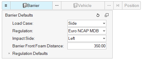
Figure 13. -
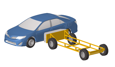
Figure 14. - Dummy Positioner: Automatic contact detection
- This new functionality enables the automatic contact detection between dummy limbs and surrounding structural components. When the contact is detected, the motion of the limb is automatically stopped and thus, avoiding intersections.
- Mechanism Tool: Automatic morphing
- This new functionality enables the automatic morphing of components using the slider joint. All morphing entities are automatically created, and the morphing happens in real time when the joint is manipulated.
-
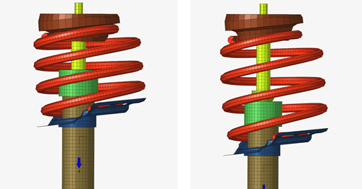
Figure 15. - Pedestrian Impact Solution
- The pre-processing the pedestrian impact regulations have been enhanced
with the following features:
- Hard parts distance contouring and offset zones creation
- Impact points refinements
-
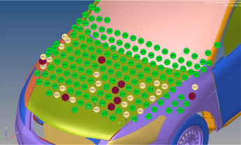
Figure 16.
Enhancements
- Graphical selection of mechanisms and dummies
- Dummies and mechanisms can be selected directly on the graphic using the Mechanism selector.
-
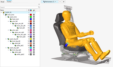 Figure 17.
Resolved Issues
- Radioss XREF are now created on import of the h3d file in the pre-simulation tools.
- LS-DYNA seatbelt extraction was not working if the break angle between the 1D belt segments was too big. This limitation is removed and a break angle control in the seatbelt extraction tool is added.