Apply Mass Panel
Use the Apply Mass panel to create a dummy connector entity to add mass to a part, or create areas of mass to represent parts not present in the CAD or FE data.
Location: connectors module
The Apply Mass panel does not create a physical join connection. Instead, the connector entity is used to distribute mass to nodes or elements. You can create a point mass to represent a part that does not exist in the model (such as a door-mounted speaker) or you can distribute several single-point masses to change the mass of an entire region in the model. You can also create non-structural masses.
When the Apply Mass panel is active, only mass-type connectors display in the modeling window; graphics for other connector types are suppressed until you exit the panel.
Location and Connection Options
| Option | Action |
|---|---|
| location | Select the FE or geometric entities to which the mass
connector entities are created.
|
| connect method | Select a method to determine which entities the mass
connector connects. Note: Only available when location is set to
nodes or points.
|
| connect what | Select an entity type to which the mass is applied. Note: Only
available when location is set to nodes or points.
|
Mass Type Options
| Option | Action |
|---|---|
| mass type | Select a mass configuration.
|
| mass | The amount of mass you wish to add. Note: The functionality of
this option is dependent on your selection for the
distribution option. Mass can be the total mass, the mass
per node, or the mass per unit of area (such as square
millimeter).
|
| type | Solver card to be created. Note: Only available when mass type
is set to nsm.
|
| NSM | Assign a NSM entity type attribute to the connector to be
created. This attribute will be written into the connector and is considered during the next realization. Upon creation of nsm connectors, the FE data (nsm group entity) is realized and a new component (CE_Mass_inc_<include name>) is created inside the current include. The newly created connectors will reside in this new component. Each include is meant to host its own CE_Mass_inc_<include name> component, and a warning will display if the component name already exists in a different include. This helps ensure that unrealizing and rerealizing nsm connectors will keep the FE data in its original include. The realization routine always looks for the content (elements) of the links and investigates whether they exclusively reference the same properties (direct or indirect) and can be condensed clearly in property references in the NSM group. The realization can behave differently
depending on this check and the defined NSM entity type
attribute.
|
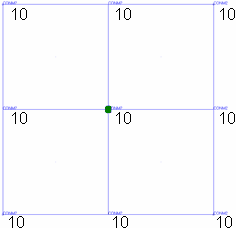
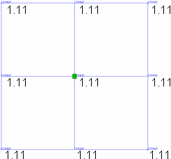
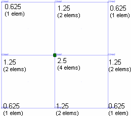
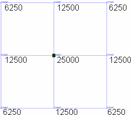
| distribution | Choose how to apply the amount specified in the mass= field
to the affected location's nodes. Note: Only available when the
mass type is set to point mass.
The examples below
all use a 9-node array with a 100mm x 100mm area (for example
10,000 square mm) and a mass of 10 grams.
|
Command Buttons
| Button | Action |
|---|---|
| create/update | Create a new mass connector entity (or entities) with the specified settings, if sufficient. Alternatively, update an existing connector (if selected as the applied mass location). |
| reject | Undo the applied mass creation or update. |
| return | Exit the panel. |