Bolt forces can be applied to bolt and nut geometries in SimSolid.
Bolts and Nuts
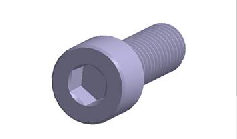
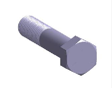
In SimSolid Cloud, bolts are automatically identified by their geometric
attributes. Bolts are required to have cylindrical bodies and a head with a
hexahedral based shape. The hex shape can be on an outer or inner diameter in the
bolt head. Nuts are identified in a similar manner using this hex based geometric
signature.Figure 1. Figure 2.
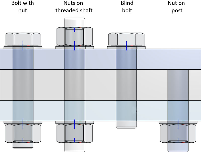
In SimSolid Cloud, tightening loads can be applied to a variety of
geometries, including the following:
Blind bolts
Bolts with nuts
Nuts on threaded rods
Nuts on a generic post or handle
Figure 3.
Relationship Between Torque M and Axial Force F
M is the maximum moment realized at the end of the tightening and it is equilibrated
by moment from friction forces in contact between nut and the structure.
Assume for simplicity that normal forces in contact are distributed evenly, so the
contact pressure is as follows:
R0 and R1 are inner and outer radii of the contact spot. Friction distributed force
is where f is a friction coefficient.
In a polar coordinate system, the elementary moment of the friction force with
respect to the bolt axis is:
Where r is the distance to axis while dR and dTet are
radius and angle differentials respectively.
Integrate the elementary moment over the contact area to obtain the
following:
This equation relates applied torque, M, and axial
force.
Axial Force
Axial force depends on the structure and bolt stiffness, and on nut placement
relative to the bolt:
K is structure stiffness factor, and D is relative
displacement.
Relative displacement can be expressed by the following:
Here, N is number of nut turns and H is thread pitch. Therefore,
(equation A).
Assume that at first analysis pass one nut turn is described (N(1)=1), and
corresponded axial force F(1) is found from the analysis. The structure stiffness
factor in this case can be defined as the following:
This implies: .
Now you can relate torque to the number of turns:
Therefore, in order to realize prescribed torque M, after the first analysis is done
with N=1, a second analysis (second convergence pass) must be performed using the
following equation:
In general, at pass (i+1) the number of turns applied is as follows:
Here, N(i) is the number of turns applied at previous passes, and F (i) is result
axial force evaluated at previous pass. These corrections for number of turns
applied are important because in the course of passes solution is refined, which
changes structure stiffness factor K in equation A above. So, K is not constant, but
depends on pass K(i).