Connections
Connections are used to define the association of different regions of interest between parts in an assembly.
- Regular Connections
- Spot welds
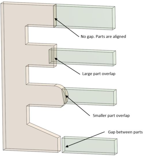
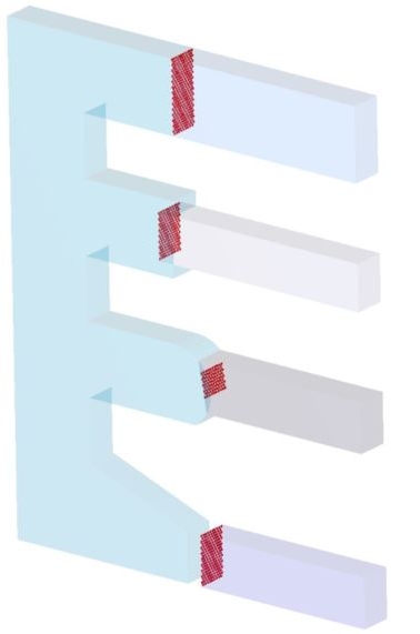
Connections define the regions of contact between parts in an assembly. In SimSolid, connections can be found automatically using two distance tolerances which define the allowable gaps and penetration between parts. A strength of SimSolid Cloud is that parts do not have to line up exactly. The user can simply adjust the two tolerances to find an acceptable connection region.
FEA versus SimSolid Cloud Connections
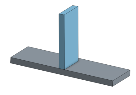
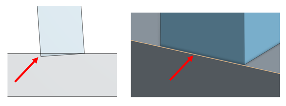
In traditional FEA, part connections can be problematic. Parts that visually appear to be connected (Figure 1) have geometric imperfections that cause numeric issues for the FEA solver (Figure 2). The result is often that the assembly must be edited or even merged into one monolithic geometry to create a single mesh. This can lead to additional problems with stress concentrations at the part boundaries and is not recommended. In SimSolid Cloud, parts are never merged.
Permitted Connections
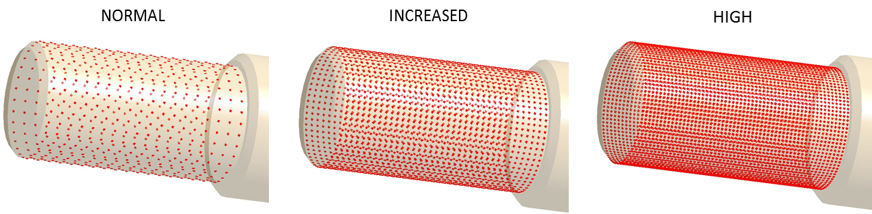
Connection Resolution
Connection resolution defines the mathematical completeness of the connection entity. Three settings are possible: Normal, Increased, and High. While details of the equations are not important to the user, be aware of regions where connections may not be adequately defined.
Considerations
- Make sure there is adequate coverage in thin or curved regions. Look at the icon density and increase it locally as required. Care must be taken that connections don’t create hinges (allow rotation between parts). This causes structural instability during the solution process.
- Large penetration tolerances can increase model stiffness and reduce the accuracy of stress near the connection boundary. Only use a penetration tolerance sufficient to cover the largest overlap. Best practice is to keep both the gap and penetration tolerances as small as possible yet still connect the parts. In most cases, common values are 1 to 2 mm for SI or 0.03 to 0.06 inch in IPS.
Problems and Solutions
- Problem: model has parts with dramatically different scales (big and small or thick and thin). Connections for the small or thin parts are not adequate.
- Solution: automatic connections only considers one global scale when making connections. In certain cases this may not provide enough detail. Use manual connections between the two problem parts. First, set gap and penetration tolerance to find connection. Next, increase resolution only if icon density is too sparse or if solution gives a numeric instability message.