Create Spot Welds
Connect two parts over a circular area on the contacting surfaces.
- There must be at least two parts directly below the clicked point OR one part with a gap and having contact with itself.
- Any gap between parts must be less than 1/2 the spot radius.
- For line spot welds, every subsequent click after the first one has to be on the same part. No cross part line spots are allowed.
- In the Project Tree, click on the Connections workbench.
-
In the pull-down menu for connection type, select Spot
weld.
Figure 1. 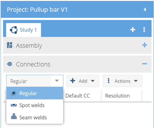
-
Click
 .
.
-
In the Create spot welds dialog, create one of the
following spot welds:
Weld Type Steps Stand-alone spot - Select the Stand alone spot radio button.
- In the modeling window, select a point on the part surface for the center of the spot weld.
Spots on line - Select the Spots on line radio button.
- For Number of spots, use the up/down arrows to select a number.
- In the modeling window, pick points to position the spots line.
Import from CSV - Select the Import from CSV radio button.
- Browse to the desired file from the file explorer.
- Click Import.
Coordinate units are in default units system.Note: Welds are only found within a tolerance of the spot weld diameter. So, for a 5mm weld, the XYZ values must be within 5mm of the part surfaces. - In the dialog, specify the Spot diameter value and units.
- Click OK.
Imported Spot Weld CSV File Format
You can create a .csv file using a spreadsheet program such as Microsoft Excel or Google Sheets. The file must have a header row and one or more additional data rows (one for each spot weld). The header row can have any number of fields but only the following are read.
CSV file format fields
- “X_Pos”, “Y_Pos”, “Z_Pos” - The X, Y and Z coordinates of the spot weld location
- “Connected Part 3” (optional) - By default SimSolid creates a spot weld between the two closest parts to the XYZ value. If a 3T weld is desired, place any alpha-numeric value here. This tells SimSolid to create 2 welds between the 3 closest parts.
In the example below, rows 2 and 3 create 2T and 3T welds between the closest
parts.
| 1 | X_Pos | Y_Pos | Z_Pos | Connected Part 3 |
|---|---|---|---|---|
| 2 | -12 | 20.7 | 0.905 | |
| 3 | -4.6 | 14.4 | 0.6 | 3T |
Format for Creating Spot Welds between Specific Parts
- “X_Pos”, “Y_Pos”, “Z_Pos” – The X, Y and Z coordinates of the spot weld location.
- "Connected part 1”, “Connected part 2” - for 2T welds – Specify the names of the parts to be connected.
- "Connected Part 3" – for 3T welds (optional) – Specify the name of the third part to be connected with spot welds.
In the example below, rows 2 and 3 create 2T and 3T spot welds between the specified parts.
In case of 3T welds, 2 welds are created in the following order: Connected part 1 –
connected part 2 and connected part 2 – connected part 3. A 3T weld creation fails
if SimSolid is unable to find weld between the specified
pairs.
| 1 | X_Pos | Y_Pos | Z_Pos | Connected Part 1 | Connected Part 2 | Connected Part 3 |
|---|---|---|---|---|---|---|
| 2 | -12 | 20.7 | 0.905 | Part 4 | Part 3 | Part 2 |
| 3 | -4.6 | 14.4 | 0.6 | Part 3 | Part 2 | Part 1 |