Contact Conditions
Contact conditions specify the type of mechanical interaction for a connection between parts.
A regular connection is always associated with a contact condition. By default, bonded contact condition is assigned to all the connections, except for bolts and nuts where sliding without friction is applied to the shank region. Contact condition editing is not allowed in such special cases.
Types
- Bonded
- Used to connect parts that act as if they were bonded and stuck together. Loads between the parts are fully transferred, and bonded components never separate from each other during the analysis. Graphic icons for bonded contact are colored red.
- Sliding Without Friction
- Allows the parts to slide relative to each other in the local tangential plane, while not allowing either inter-penetration or separation of the connected surfaces. Only normal to the surface forces are transferred between the parts. This assumes a frictionless sliding surface. Graphic icons for sliding contact are colored yellow.
- Separating
- The parts may partially or completely separate from each other under the
load. The forces transfer only through the connected regions. Friction
coefficient defines the sticking/sliding threshold. The friction
coefficient must be between 0.0 and 1.0, typical values are 0.1 to 0.2.
Value of 0 indicates sliding and 1 indicates bonded. This is a
non-linear solution and takes more time than simple bonded or sliding
contact. Graphic icons for separating contact are colored
green.
Separating contact can also be applied to parts with initial gap/penetration. In such cases, the parts can be separated but cannot be closed. The final gap between the parts is always either equal to or greater than the initial gap between the parts.
- Disable Contact
- The parts act as if they were disconnected; They may separate from each other or even penetrate into each other under the load. The applied forces do not transfer through the disabled contact. Graphic icons for disabled contact are colored black.
Comments
- In thermal analysis, bonded contacts have no resistance and disabled contacts are insulated.
Edit Contact Conditions
Specify the type of mechanical interaction for a connection between parts.
- In the Project Tree, expand the Connections workbench.
- Right-click on the connection you wish to edit and select Edit default contact condition from the context menu.
- In the dialog, choose a contact condition type.
-
Click OK.
The contact condition is applied at the chosen connection for all analyses.Note: Contact conditions can be customized at any analysis level. For more information, go to Review Part Contact Conditions.Note: Contact conditions can be customized at any analysis level. For more information, go to Review Part Contact Conditions.
Review Part Contact Conditions
Review contact conditions of connections in selected analysis.
- In the modeling window, right-click on a part of the model.
-
In the context menu, select Contact
conditions.
Note: This option is greyed out if no analysis exists in the project.A dialog opens and shows a list of all connections and contact conditions for the selected part and analysis. Contact conditions for specific analysis or all analysis can be edited from this dialog.
- In the drop-down menu, select an analysis to edit its contact conditions.
- Select a connection to see it highlighted on the model.
-
On the Connections workbench, next to the desired
connection select
 (Action menu) > Edit.
Tip: You can also double-click on the connection in the modeling window to edit.
(Action menu) > Edit.
Tip: You can also double-click on the connection in the modeling window to edit. - In the dialog, choose a contact condition type.
- Click OK.
- Optional:
Select the Connections between parts in list only check
box to only display connections between selected parts.
By default, all connections associated with both parts are displayed.
- Optional:
Select the Apply to all structural analyses check box to
apply changes to all structural analyses.
By default, only the analysis selected in the drop-down menu is modified.
Custom Contact Conditions
Create analysis-specific contact conditions.
Initially, a default set of contact conditions are contained in the Connections panel. These are used by all analyses but may be superseded by analysis specific contact conditions.
- In the Project Tree, click on the Analysis Workbench.
-
Click the (Action menu) button beside the desired analysis,
then choose Contact conditions from the menu.
Figure 1. 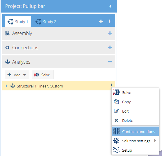
-
In the modeling window, select any part on the
model.
The associated connections and contact conditions are displayed, and you have the option to edit.
Figure 2. 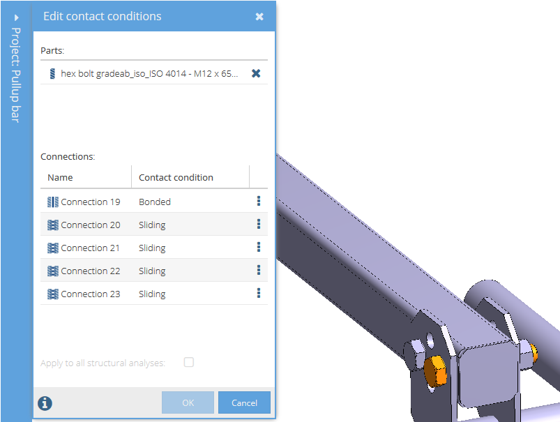
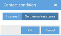
Thermal Contact Conditions
Apply thermal specific boundary conditions between parts in an assembly.
Two values are possible: no thermal resistance or insulated. No thermal resistance is the default condition and means that full heat transfer occurs through the part connection. Insulated means the opposite. No heat transfer occurs.
- In the Project Tree, click on the Thermal Analysis Workbench.
-
Click the (Action menu) button beside the desired analysis,
then choose Contact conditions from the menu.
-
In the dialog, toggle either no thermal resistance or
insulated.
Figure 3.