/MONVOL/FVMBAG (Obsolete)
Block Format Keyword Describes the airbag with FVMBAG type. The input is similar to AIRBAG type.
Format
| (1) | (2) | (3) | (4) | (5) | (6) | (7) | (8) | (9) | (10) |
|---|---|---|---|---|---|---|---|---|---|
| /MONVOL/FVMBAG/monvol_ID/unit_ID | |||||||||
| monvol_title | |||||||||
| surf_IDex | |||||||||
| Ascalet | AscaleP | AscaleS | AscaleA | AscaleD | |||||
| Pext | T0 | Iequi | Ittf | ||||||
| cpai | cpbi | cpci | |||||||
| (1) | (2) | (3) | (4) | (5) | (6) | (7) | (8) | (9) | (10) |
|---|---|---|---|---|---|---|---|---|---|
| Njet |
| (1) | (2) | (3) | (4) | (5) | (6) | (7) | (8) | (9) | (10) |
|---|---|---|---|---|---|---|---|---|---|
| cpa | cpb | cpc | |||||||
| fct_IDmas | Iflow | Fscalemas | fct_IDT | FscaleT | sens_ID | ||||
| Isjet | |||||||||
| fct_IDvel | Fscalevel | ||||||||
| (1) | (2) | (3) | (4) | (5) | (6) | (7) | (8) | (9) | (10) |
|---|---|---|---|---|---|---|---|---|---|
| Nvent |
| (1) | (2) | (3) | (4) | (5) | (6) | (7) | (8) | (9) | (10) |
|---|---|---|---|---|---|---|---|---|---|
| surf_IDv | Avent | Bvent | Itvent | ||||||
| Tvent | Pdef | tPdef | fct_IDV | FscaleV | IdtPdef | ||||
| fct_IDt | fct_IDP | fct_IDA | Fscalet | FscaleP | FscaleA | ||||
| fct_IDt' | fct_IDP' | fct_IDA' | Fscalet' | FscaleP' | FscaleA' | ||||
| (1) | (2) | (3) | (4) | (5) | (6) | (7) | (8) | (9) | (10) |
|---|---|---|---|---|---|---|---|---|---|
| Vx3 | Vy3 | Vz3 | |||||||
| Vx1 | Vy1 | Vz1 | |||||||
| X0 | Y0 | Z0 | |||||||
| L1 | L2 | L3 | |||||||
| Nb1 | Nb2 | Nb3 | grbrc_ID | surf_IDin | Iref | ||||
| (1) | (2) | (3) | (4) | (5) | (6) | (7) | (8) | (9) | (10) |
|---|---|---|---|---|---|---|---|---|---|
| Igmerg | Cgmerg | Cnmerg | Ptole | ||||||
| qa | qb | Hmin | |||||||
| Ilvout | Nlayer | Nfacmax | Nppmax | Ifvani | |||||
Definitions
| Field | Contents | SI Unit Example |
|---|---|---|
| monvol_ID | Monitored volume
identifier (Integer, maximum 10 digits) |
|
| unit_ID | Unit Identifier (Integer, maximum 10 digits) |
|
| monvol_title | Monitored volume
title (Character, maximum 100 characters) |
|
| surf_IDex | External surface
identifier 1 (Integer) |
|
| Ascalet | Abscissa scale factor for
time based functions Default = 1.0 (Real) |
|
| AscaleP | Abscissa scale factor for
pressure based functions Default = 1.0 (Real) |
|
| AscaleS | Abscissa scale factor for
area based functions Default = 1.0 (Real) |
|
| AscaleA | Abscissa scale factor for
angle based functions Default = 1.0 (Real) |
|
| AscaleD | Abscissa scale factor for
distance based functions Default = 1.0 (Real) |
|
| Pext | External
pressure (Real) |
|
| T0 | Initial
temperature. Default = 295 (Real) |
[K] |
| Iequi | Initial thermodynamic
equilibrium flag.
(Integer) |
|
| Ittf | Venting time shift flag.
Active only when injection sensor is specified.
|
|
| Ratio of specific heats at
initial temperature 5
(Real) |
||
| cpai | cpa
coefficient in the relation
cpi(T) (Real) |
|
| cpbi | cpb
coefficient in the relation
cpi(T) (Real) |
|
| cpci | cpc
coefficient in the relation
cpi(T) (Real) |
|
| Njet | Number of
injectors (Integer) |
|
| Ratio of specific heats
(Real) |
||
| cpa | cpa
coefficient in the relation cp(T) (Real) |
|
| cpb | cpb
coefficient in the relation cp(T) (Real) |
|
| cpc | cpc
coefficient in the relation cp(T) (Real) |
|
| fct_IDmas | Mass of injected gas
versus time identifier (Integer) |
|
| Iflow | Mass versus time function
input type flag
(Integer) |
|
| Fscalemas | Scale factor on mass
function Default = 1.0 (Real) |
or |
| fct_IDT | Temperature of injected
gas versus time identifier (Integer) |
|
| FscaleT | Temperature scale
factor Default = 1.0 (Real) |
|
| sens_ID | Sensor identifier to start
injections (Integer) |
|
| Isjet | Injector surface
identifier (must be different for each
injectors) (Integer) |
|
| fct_IDvel | Injected gas velocity
identifier (Integer) |
|
| Fscalevel | Injected gas scale
factor Default = 1.0 (Real) |
|
| Nvent | Number of vent
holes (Integer) |
|
| surf_IDv | Vent holes membrane
surface (Real) or porous surface identifier (Integer) |
|
| Avent | If
surf_IDv ≠
0: scale factor on surface. Default = 1.0 If surf_IDv = 0: surface of vent holes. Default = 0.0 (Real) |
, if surf_IDV = 0 |
| Bvent | If
surf_IDv ≠
0: scale factor on impacted surface Default = 1.0 If surf_IDv = 0: Bvent is reset to 0 Default = 0.0 (Real) |
, if surf_IDV = 0 |
| Itvent | Venting formulation 7
(Integer) |
|
| Tvent | Start time for
venting Default = 0.0 (Real) |
|
| Pressure difference to
open vent hole membrane (
=
Pdef - Pext) (Real) |
||
| Minimum duration pressure
exceeds Pdef to
open vent hole membrane (Real) |
||
| fct_IDV | Outflow velocity function
identifier (Integer) |
|
| FscaleV | Scale factor on
fct_IDV Default = 1.0 (Real) |
|
| IdtPdef | Time delay flag when
is reached:
|
|
| fct_IDt | Porosity vs time function
identifier (Integer) |
|
| fct_IDP | Porosity vs pressure
function identifier (Integer) |
|
| fct_IDA | Porosity vs area function
identifier (Integer) |
|
| Fscalet | Scale factor for
fct_IDt Default = 1.0 (Real) |
|
| FscaleP | Scale factor for
fct_IDP Default = 1.0 (Real) |
|
| FscaleA | Scale factor for
fct_IDA Default = 1.0 (Real) |
|
| fct_IDt' | Porosity vs time when
contact function identifier (Integer) |
|
| fct_IDP' | Porosity vs pressure when
contact function identifier (Integer) |
|
| fct_IDA' | Porosity vs impacted
surface function identifier (Integer) |
|
| Fscalet' | Scale factor for
fct_IDt' Default = 1.0 (Real) |
|
| FscaleP' | Scale factor for
fct_IDP' Default = 1.0 (Real) |
|
| FscaleA' | Scale factor for
fct_IDA' Default = 1.0 (Real) |
|
| Vx3 | X component of vector
V3 (in global
frame) (Real) |
|
| Vy3 | Y
component of vector V3 (in global
frame) (Real) |
|
| Vz3 | Z
component of vector V3 (in global
frame) (Real) |
|
| Vx1 | X
component of vector V1 (in global
frame) (Real) |
|
| Vy1 | Y
component of vector V1 (in global
frame) (Real) |
|
| Vz1 | Z
component of vector V1 (in global
frame) (Real) |
|
| X0 | X
coordinate of local origin O (in global frame) (Real) |
|
| Y0 | Y
coordinate of local origin O (in global frame) (Real) |
|
| Z0 | Z
coordinate of local origin O (in global frame) (Real) |
|
| L1 | Length
L1 (Real) |
|
| L2 | Length
L2 (Real) |
|
| L3 | Length
L3 (Real) |
|
| Nb1 | Number of finite volumes
in direction 1 Default = 1 (Integer) |
|
| Nb2 | Number of finite volumes
in direction 2 Default = 1 (Integer) |
|
| Nb3 | Number of finite volumes
in direction 3 Default = 1 (Integer) |
|
| grbric_ID | User-defined solid group
identifier (Integer) |
|
| surf_IDin | Internal surfaces
identifier 25 (Integer) |
|
| Iref | Flag for applying the
automated FVM mesh on the reference geometry 24
(Integer) |
|
| Igmerg | Global merging formulation
flag 19 Default = 1 (Integer) |
|
| Cgmerg | Factor for global merging
19 Default = 0.02 (Real) |
|
| Cnmerg | Factor for neighborhood
merging 19 (Real) |
|
| Ptole | Tolerance for finite
volume identification Default = 10-5 (Real) |
|
| qa | Quadratic bulk
viscosity Default = 0.0 (Real) |
|
| qb | Linear bulk
viscosity Default = 0.0 (Real) |
|
| Hmin | Minimum height for
triangle permeability 21 (Real) |
|
| Ilvout | Output level: 0 or
1 Default = 0 (Integer) |
|
| Nlayer | Estimated number of layers
in airbag folding along direction V3
22 Default = 10 (Integer) |
|
| Nfacmax | Estimated maximum number
of airbag segments concerned by a finite volume in the first
automatic meshing step. Default = 20 (Integer) |
|
| Nppmax | Estimated maximum number
of vertices of a polygon Default = 20 (Integer) |
|
| Ifvani | Write finite volumes in
Radioss Starter Animation A000 File flag
(Integer) |
Comments
- surf_IDex must be defined using segments associated with 4-nodes or 3-nodes shell elements (possibly void elements).
- The volume must be closed and the normals must be oriented outwards.
- Abscissa scale factors
are used to transform abscissa units in airbag functions, for example:
(1) where, t is the time.(2) Where, p is the pressure.
- The initial pressure is set to Pext.
- If = 0, the characteristics of the gas initially filling the airbag are set to the characteristics of the gas by the first injector.
- The gas flow in
FVMBAG is solved using finite volumes.
Some of these finite volumes can be entered by you through a group of solids, located inside the airbag and filling a part or the total internal volume. If there still exists a part of the internal volume which is not discretized by user-defined solids, an automatic meshing procedure produces the remaining volumes. This can be used for example to model a canister.
A finite volume consists in a set of triangular facets. Their vertices do not necessarily coincide with the nodes of the airbag. The airbag envelope can be modeled with 4-node or 3-node membranes; however, 3-nodes are recommended.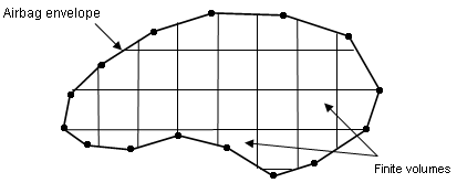
Figure 1.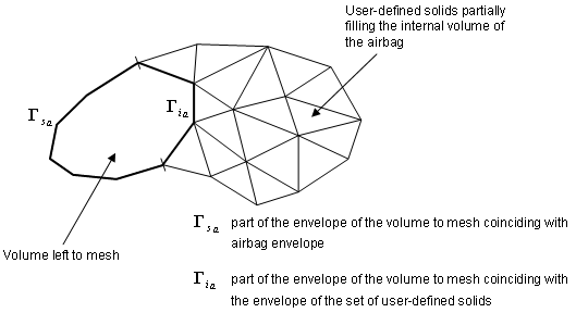
Figure 2. - The exit velocity is
given by:
(3) The mass out flow rate is given by:(4) The energy flow rate is given by:(5) The venting velocity is computed by:(6) - Vent hole membrane is deflated if T > Tvent or if the pressure exceeds Pdef during more than .
- If
surf_IDv ≠ 0
(surf_IDv is defined).
(7) Where, A is the Area of surface surf_ID and A0 is the initial Area of surface surf_IDv.
- If
surf_IDv = 0
(surf_IDv is not defined) vent
hole is ignored.
(8) - Functions fct_IDt and fct_IDP are assumed to be equal to 1, if they are not specified (null identifier).
- Function fct_IDA is assumed as the fct_IDA(A/A0) = 1, if it is not specified.
- Vent holes surface is
computed as follows:
(9) with impacted surface:(10) and non-impacted surface:(11) Where for each element e of the vent holes surf_IDv, nc(e) means the number of impacted nodes among the n(e) nodes defining the element.
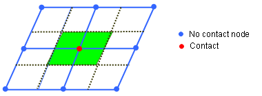
Figure 3. From Nodes Contact to Impacted/Non-impacted Surface - Functions fct_IDt' and fct_IDP' are assumed to be equal to 1, if they are not specified (null identifier).
- In order to use porosity during contact, flag IBAG must be set to 1 in the interfaces concerned (Line 3 of interface Type 5 and Type 7). If not, the nodes impacted into the interface are not considered as impacted nodes in the previous formula for Aimpacted and Anon_impacted.
- Automatic finite
volume meshing parameters.
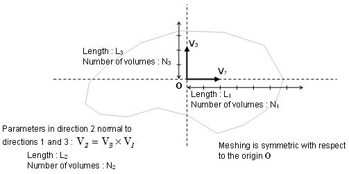
Figure 4. - The finite volumes are
generated in two steps.
- The first step generates vertices lying exclusively on the envelope of
the airbag. This allows to update the finite volume along with the
deformation of the envelope and correspond to the following procedure
(displayed in 2D for purpose of clarity):
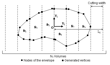
Figure 5.This procedure requires the input of the direction V3, named cutting direction, and of the direction V1. A second direction V2 in the plan normal to the cutting direction will be computed. In order to position the finite volumes and to determine the cutting width in both direction V1 and V2, an origin O must be provided as well as a length Li, counted both positively and negatively from the origin, and a number of steps Ni. The cutting width is then given by Wi = 2Li / Ni
It is required that the box drawn in the horizontal plane (normal to V3 ) by the origin O and the length Li, counted both positively and negatively from O, includes the bounding-box of the envelope of the volume to mesh projected in this plane. This is necessary to ensure that this volume in entirely divided into finite volumes.
- The second step performs horizontal cutting of the finite volumes, and
may be useless in many cases of tightly folded airbags. It is especially
required when injection is made in a canister filled by the injected gas
before unfolding the airbag.This second step may generate vertices located inside the airbag. In order for them to be moved along with the inflation of the airbag, each is attached to a vertical segment (parallel to direction V3) between two vertices lying on the envelope of the airbag (Figure 6). The local coordinates of the vertex within its reference segment remain constant throughout the inflation process.
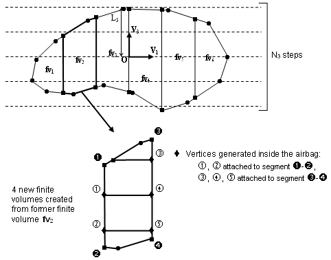
Figure 6.The horizontal cutting width is given by W3 = 2L3 / N3. It is not necessary that the segment given in the V3 direction by the origin O and length L3, counted both positively and negatively, includes the bounding-box of the envelope of the volume to mesh projection on the V3 direction, since at the second step only existing finite volumes are cut.
- The first step generates vertices lying exclusively on the envelope of
the airbag. This allows to update the finite volume along with the
deformation of the envelope and correspond to the following procedure
(displayed in 2D for purpose of clarity):
- Actual vector V1 used for automatic meshing is obtained after orthogonalization of the input vector with respect to vector V3.
- When a finite volume
fails during the inflation process of the airbag (volume becoming negative, internal
mass or energy becoming negative), it is merged to one of its neighbors so that the
calculation can continue. Two merging approaches are used:
- Global merging: a finite volume is merged if its volume becomes less than a certain factor multiplying the mean volume of all the finite volumes. The flag Igmerg determines if the mean volume to use is the current mean volume (Igmerg =1) or the initial mean (Igmerg =2). The factor giving the minimum volume from the mean volume is Cgmerg.
- Neighborhood merging: a finite volume is merged if its volume becomes less than a certain factor multiplying the mean volume of its neighbors. The factor giving the minimum volume from the mean volume is Cnmerg.
- In the case of both Cgmerg and Cnmerg are not equal to 0, means both merging approach will be used simultaneously. In case of a strong shock, it is recommended to set qa = 1.1 and qb = 0.05.
- When two layers of fabric are physically in contact, there should be no possible flow between finite volumes, which is numerically not the case because of interface gap. Hmin represents a minimum height for the triangular facets below which the facet is impermeable. Its value should be close to the gap of the self-impacting interface of the airbag.
- Nlayer, Nfacmax, Nppmax are memory parameters that help the finite volume creation process. Changing their value cannot cause the calculation to stop. Increasing the leads to a higher amount of memory and a smaller computation time for automatic meshing.
- During the finite volume creation process, plane polygons are first created, which are then assembled into closed polyhedra and decomposed into triangular facets. Nppmax is the maximum number of vertices of these polygons.
- Iref set to 1 only works with a reference geometry based on /REFSTA (not yet supported if the reference geometry is based on /XREF) for monitored volumes types FVMBAG or FVMBAG1.
- Only applicable to the Finite Volume Method, used to take internal surfaces or baffles into account as obstacles to the gas flow inside the monitored volume. Internal surfaces are taken into account in FVM only if the monitored volume is filled with solid elements, like TETRA4 (possibly HEXA and PENTA) with nodes coinciding with the monitored volume external and internal surface nodes (these solids must be declared in grbrick_ID). A porosity ranging from 0: no porosity up to 1: full porosity (vent) can be applied to internal surface fabrics only if their material model is LAW19. Injector surface can also be defined on an internal surface in which case the gas flow direction is opposite to the internal surface normal orientation.
- If an element of a
vent hole surface (surf_IDv) belongs to an injector
(surf_IDinj) it will be ignored from the vent hole. A
constant c correction factor f computed at time t=0 is applied to
the total vent hole surface:
(12)