/MONVOL/AIRBAG (Obsolete)
Block Format Keyword Describes the airbag monitored volume type.
Format
| (1) | (2) | (3) | (4) | (5) | (6) | (7) | (8) | (9) | (10) |
|---|---|---|---|---|---|---|---|---|---|
| /MONVOL/AIRBAG/monvol_ID/unit_ID | |||||||||
| monvol_title | |||||||||
| surf_IDex | |||||||||
| Ascalet | AscaleP | AscaleS | AscaleA | AscaleD | |||||
| Pext | T0 | equi | Ittf | ||||||
| cpai | cpbi | cpci | |||||||
| (1) | (2) | (3) | (4) | (5) | (6) | (7) | (8) | (9) | (10) |
|---|---|---|---|---|---|---|---|---|---|
| Njet |
| (1) | (2) | (3) | (4) | (5) | (6) | (7) | (8) | (9) | (10) |
|---|---|---|---|---|---|---|---|---|---|
| cpa | cpb | cpc | |||||||
| fct_IDmas | Iflow | Fscalemas | fct_IDT | FscaleT | sens_ID | ||||
| Ijet | node_ID1 | node_ID2 | node_ID3 | ||||||
| (1) | (2) | (3) | (4) | (5) | (6) | (7) | (8) | (9) | (10) |
|---|---|---|---|---|---|---|---|---|---|
| fct_IDPt | fct_IDP | fct_IDP | Fscalept | Fscalep | Fscalep | ||||
| (1) | (2) | (3) | (4) | (5) | (6) | (7) | (8) | (9) | (10) |
|---|---|---|---|---|---|---|---|---|---|
| Nvent |
| (1) | (2) | (3) | (4) | (5) | (6) | (7) | (8) | (9) | (10) |
|---|---|---|---|---|---|---|---|---|---|
| surf_IDv | Avent | Bvent | Tstop | ||||||
| Tvent | fct_IDV | FscaleV | IdtPdef | ||||||
| fct_IDt | fct_IDP | fct_IDA | Fscalet | FscaleP | FscaleA | ||||
| fct_IDt' | fct_IDP' | fct_IDA' | Fscalet' | FscaleP' | FscaleA' | ||||
Definitions
| Field | Contents | SI Unit Example |
|---|---|---|
| monvol_ID | Monitored volume
identifier (Integer, maximum 10 digits) |
|
| unit_ID | Unit Identifier (Integer, maximum 10 digits) |
|
| monvol_title | Monitored volume
title (Character, maximum 100 characters) |
|
| surf_IDex | External surface
identifier 1 (Integer) |
|
| Ascalet | Abscissa scale factor for
time based functions Default = 1.0 (Real) |
|
| AscaleP | Abscissa scale factor for
pressure based functions Default = 1.0 (Real) |
|
| AscaleS | Abscissa scale factor for
area based functions Default = 1.0 (Real) |
|
| AscaleA | Abscissa scale factor for
angle based functions Default = 1.0 (Real) |
|
| AscaleD | Abscissa scale factor for
distance based functions Default = 1.0 (Real) |
|
| mat_ID | Initial gas material
identifier (/MAT/GAS) (Real) |
|
| Volumetric
viscosity Default = 0.01 (Real) |
||
| Pext | External
pressure (Real) |
|
| T0 | Initial
temperature. Default = 295 (Real) |
|
| Iequi | Initial thermodynamic
equilibrium flag.
(Integer) |
|
| Ittf | Venting time shift flag.
Active only when injection sensor is specified.
|
|
| Ratio of specific heats at
initial temperature
(Real) |
||
| cpai | cpa
coefficient in the relation
cpi(T) (Real) |
|
| cpbi | cpb
coefficient in the relation
cpi(T) (Real) |
|
| cpci | cpc
coefficient in the relation
cpi(T) (Real) |
|
| Njet | Number of
injectors (Integer) |
|
| Ratio of specific heats
(Real) |
||
| cpa | cpa
coefficient in the relation cp(T) (Real) |
|
| cpb | cpa
coefficient in the relation cp(T) (Real) |
|
| cpc | cpa
coefficient in the relation cp(T) (Real) |
|
| surf_IDv | Vent holes membrane
surface identifier (Integer) |
|
| Avent | If
surf_IDv ≠
0: scale factor on surface Default = 1.0 If surf_IDv = 0: surface of vent holes Default = 0.0 (Real) |
, if surf_IDV = 0 |
| Bvent | If
surf_IDv ≠
0: scale factor on impacted surface Default = 1.0 If surf_IDv = 0: Bvent is reset to 0. Default = 0.0 (Real) |
, if surf_IDV = 0 |
| Tstop | Stop time for
venting Default = 1E+30 (Real) |
|
| Tvent | Start time for
venting Default = 0.0 (Real) |
|
| Pressure difference to
open vent hole membrane (
=
Pdef - Pext) (Real) |
||
| Minimum duration pressure
exceeds Pdef to
open vent hole membrane (Real) |
||
| fct_IDV | Outflow velocity function
identifier (Integer) |
|
| FscaleV | Scale factor on
fct_IDV Default = 1.0 (Real) |
|
| IdtPdef | Time delay flag when
is reached:
|
|
| fct_IDt | Porosity vs time function
identifier (Integer) |
|
| fct_IDP | Porosity vs pressure
function identifier (Integer) |
|
| fct_IDA | Porosity vs area function
identifier (Integer) |
|
| Fscalet | Scale factor for
fct_IDt Default = 1.0 (Real) |
|
| FscaleP | Scale factor for
fct_IDP Default = 1.0 (Real) |
|
| FscaleA | Scale factor for
fct_IDA Default = 1.0 (Real) |
|
| fct_IDmas | Mass of injected gas vs
time function identifier (Integer) |
|
| Iflow | Mass vs time function
input type flag
(Integer) |
|
| Fscalemas | Mass function scale
factor Default = 1.0 (Real) |
or |
| fct_IDT | Temperature of injected
gas vs time function identifier (Integer) |
|
| FscaleT | Temperature function scale
factor Default = 1.0 (Real) |
|
| sens_ID | Sensor
identifier (Integer) |
|
| Ijet | Jetting flag
(Integer) |
|
| node_ID1, node_ID2, node_ID3 | Node identifiers
N1,
N2, and
N3 for jet shape
definition (Integer) |
|
| fct_IDPt | If
Ijet =
1: identifier of the function number defining
(Integer) |
|
| fct_IDP | If
Ijet =
1: identifier of the function number defining
) (Integer) |
|
| fct_IDP | If
Ijet =
1: identifier of the function number defining
(Integer) |
|
| FscalePt | If
Ijet =
1: scale factor for
fct_IDPt Default = 1.0 (Real) |
|
| FscaleP | If
Ijet =
1: scale factor for
fct_IDP
Default = 1.0 (Real) |
|
| FscaleP | If
Ijet =
1: scale factor for
fct_IDP
Default = 1.0 (Real) |
|
| Nvent | Number of vent
holes (Integer) |
|
| fct_IDt' | Porosity vs time when
contact function identifier (Integer) |
|
| fct_IDP' | Porosity vs pressure when
contact function identifier (Integer) |
|
| fct_IDA' | Porosity vs impacted
surface function identifier (Integer) |
|
| Fscalet' | Scale factor for
fct_IDt' Default = 1.0 (Real) |
|
| FscaleP' | Scale factor for
fct_IDP' Default = 1.0 (Real) |
|
| FscaleA' | Scale factor for
fct_IDA' Default = 1.0 (Real) |
Comments
- surf_IDex must be defined using segments associated with 4-nodes or 3-nodes shell elements (possibly void elements).
- The volume must be closed and the normals must be oriented outwards.
- Abscissa scale factors
are used to transform abscissa units in airbag functions, for
example:
(1) Where, t is the time.
For example, if your input data is in [ms], but you need a data in [s], you could set Ascale to 0.001.(2) Where, p is the pressure.
- Initial pressure is set to Pext.
- Initial thermodynamic
equilibrium is written at time zero
(Iequi =0)
or at beginning of jetting (Iequi
=1), based on the following equation with respect to the volume
at time zero, or the volume at beginning of jetting:
where, M0 is the mass of gas initially filling the airbag, Mi is the molar mass of the gas initially filling the airbag, and R is the gas constant depending on the units system.
(3) - Ratio of specific heats
at constant pressure per mass unit
cpi of the gas initially
filling the airbag is quadratic versus temperature:
(4) - Gas constant at initial
temperature
i must be related to specific
heat per mass unit at initial temperature and molar mass of the gas initially
filling the airbag with respect to the following relation:
(5) Where, Mi is the molar mass of the gas initially filling the airbag, and R is the gas constant depending on the units system.(6) - The characteristics of the gas initially filling the airbag must be defined (no default) and must be equal for each communicating airbag.
- If i = 0, the characteristics of the gas initially filling the airbag are set to the characteristics of the gas provided by the first injector.
- Ratio of specific
heats at constant pressure per mass unit
cpi of the gas is quadratic
with regard to the temperature:
(7) - Gas constant at
initial temperature
must be related to specific heat per mass unit at initial
temperature and molar mass of the with respect to the following
relation:
(8) Where,- M
- Molar mass of the gas
- R
- Gas constant depending on the units system
(9) - If jetting is used, an
additional
Pjet pressure is applied to
each element of the airbag:
(10) - With
being the normalized vector between the projection
of the center of the element upon segment (node_ID1 and node_ID3) and the center of the
element;
the angle between vectors MN2
and
(in degrees),
is the distance between the center of the element and its
projection upon segment (node_ID1 and node_ID3 ).The projection of a point upon segment (node_ID1 and node_ID3) is defined as the projection of the point in direction MN2 upon the line (node_ID1 and node_ID3) if it lies inside the segment (node_ID1 and node_ID3). If this is not the case, the projection of the point upon segment (node_ID1 and node_ID3) is defined as the closest node node_ID1 or node_ID3.
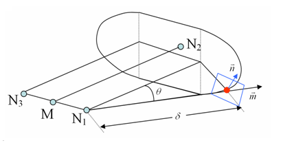
Figure 1. Dihedral Shape of the Jetwith M between N1 and N3
- If node_ID3 = 0, node_ID3 is set to node_ID1 and the dihedral shape is reduced to a conical shape.
- If
fct_IDV = 0:
isenthalpic outflow is assumed, else Chemkin model is used and outflow velocity
is:
(11) - Isenthalpic model
Venting or the expulsion of gas from the volume, is assumed to be isenthalpic.
The flow is also assumed to be unshocked, coming from a large reservoir and through a small orifice with effective surface area, A.
Conservation of enthalpy leads to velocity, u, at the vent hole. The Bernouilli equation is then written as:
(monitored volume) (vent hole)
Applying the adiabatic conditions:
(monitored volume) (vent hole)
Where, P is the pressure of gas into the airbag and is the density of gas into the airbag.
Therefore, the exit velocity is given by:(12) For supersonic flows the outlet velocity is determined as described in 10.4.4.1 of the Theory Manual.
The mass out flow rate is given by:(13) The energy flow rate is given by:(14) Where, V is the airbag volume and E is the internal energy of gas into the airbag.
- Chemkin model
(15) Where, is the density of the gas within the airbag.
- Isenthalpic model
- Vent holes surface is
computed as follows:
(16) (17) with impacted surface:(18) and non-impacted surface:(19) Where for each element e of the vent holes surf_IDv, nc(e) means the number of impacted nodes among the n(e) nodes defining the element.
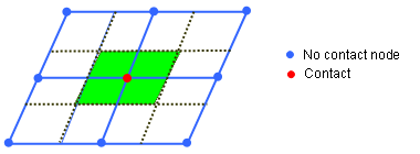
Figure 2. From Nodes Contact to Impacted/Non-impacted Surface - Functions fct_IDt' and fct_IDP' are assumed to be equal to 1, if they are not specified (null identifier).
- Function fct_IDA' is assumed as the fct_IDA'(A) = A, if it is not specified.
- In order to use porosity during contact, flag IBAG must be set to 1 in the interfaces concerned (Line 3 of interface Type 5 and Type 7). If not, the nodes impacted into the interface are not considered as impacted nodes in the previous formula for Aimpacted and Anon_impacted.
- When defining venting,
there are some limitations concerning the definition of airbag surface and surface venting:
- The airbag external surface should be built only from shells and 3-nodes shell elements.
- The airbag external surface can not be defined with option /SURF/SEG (or with option /SURF/SURF if a sub-surface is defined with option /SURF/SEG).
- Same restriction applies to vent hole surface.
- Shells and 3-nodes shell elements included in vent hole surface have to also be included in external surface.
- Vent hole membrane is deflated if T > Tvent or if the pressure exceeds Pdef during more than .