Rear Twist Beam
A rear twist beam suspension is also known as “torsion beam axle” suspension. They are named twist axles, because the axle must twist when the vehicle rolls. The beam holds the two trailing arms together, and provides the roll stiffness of the suspension by twisting as the two trailing arms move relative to each other. This suspension is widely used on small inexpensive passenger cars.
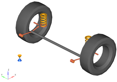
Figure 1. Rear Twist Beam Suspension
- Beam at the bushing center.
- Beam partway between the bushings and the wheel center.
- Cross beam at the wheel centers.
The figure shown above is a rear wheel twist beam suspension system of the second type. The model can be easily modified to represent all three types of axles.
Model Use
- The wheel body represents the mass and inertia of the tire and the rim.
- The wheel hub body represents the mass and inertia of other rotating bodies such as a brake rotor, but not the half-shafts if the suspension is driven. The wheel hub and brake rotor have no associated graphics.
- The wheel and wheel hub parts use the Wheel CG location as the center of gravity.
- Each body’s Center of Gravity (CG) is estimated from the body’s geometry. The formulas are coded into the point panel and can be seen via the graphical user interface. If more accurate CG locations are available they should be used.
- The model contains beams to represent the twist portion of the axle. This is a good representation of the axle early in a vehicle program. As a design is refined, the axle twist should be represented by a flexible body.
- A wide variety of combinations of suspensions and subsystems can be built using the
Assembly Wizard. You are encouraged to build systems and
understand the resulting model using the graphical user interface.
When building a new suspension model, build the model with all of the optional systems (stabilizer bar, etc) included in the model. Immediately turn off the systems using the Project Browser and run an analysis on the base suspension to ensure it solves properly. As data becomes available for the optional systems; activate those systems and populate them with data.
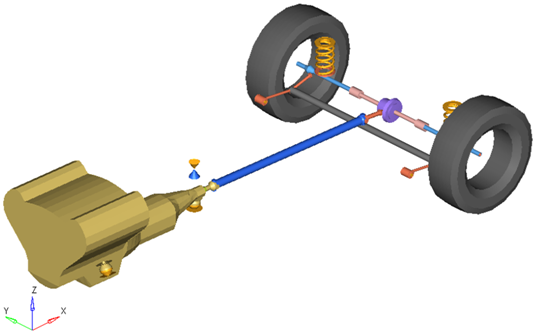
Figure 2. Rear-Half-Vehicle Model Employing a Twist Beam Suspension and a Powertrain
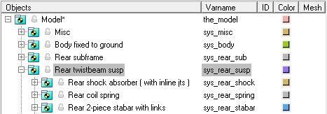
Figure 3. Browser View of a Rear-Half-Vehicle Model Systems and Subsystems Employing a Twist Beam Suspension
Attachments
| Entity | Attaches To |
|---|---|
| Trailing Arm, Track Bar | Default: Sub-frame No subframe: Vehicle body No vehicle body: Ground |
Points
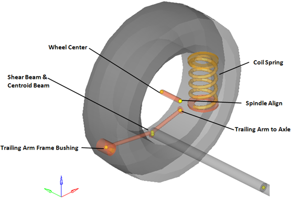
Figure 4. Right Side Principal Points – Rear Twist Beam Suspension
Bodies
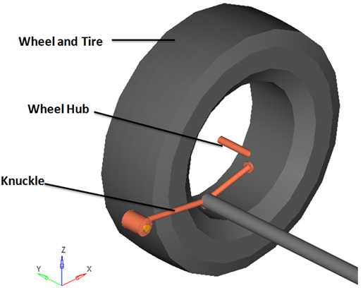
Figure 5. Right Side Bodies – Rear Trailing Arm Suspension
- The wheel hub body has no associated graphics and therefore is not visible in the image above.
- Only right side bodies are shown (as the left side bodies are symmetrical), and the coil spring has been omitted from the image above for clarity.
Bushings and Joints
| Label | Type | Body 1 | Body 2 | Point | Notes |
|---|---|---|---|---|---|
| Wheel Spindle Joint | Revolute | Wheel Hub | Knuckle | Wheel Center | |
| Wheel Hub Fixed Joint | Fixed | Wheel | Wheel Hub | Wheel Center | When the Spindle compliance option is set to Yes, the joint type changes to universal. |
| Trailing Arm Bush | Revolute | Knuckle | Vehicle Body | Trail Frame |
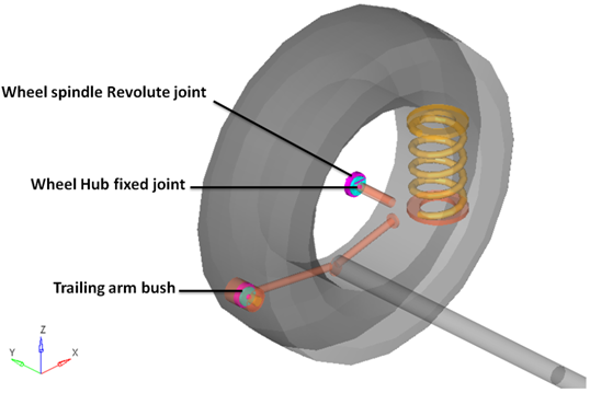
Figure 6. Right Side Joints and Bushings: Rear Twist Beam Suspension
Beams
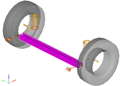
Figure 7. Beams used in the Rear Twist Beam Suspension