Rear Trailing Arm
The rear trailing arm suspension is an independent rear suspension system in which the wheel is attached to the trailing end of an arm that pivots on a bushing (this allows the wheel to move up and down). The suspension design requires a trailing arm that is flexible in order to work. A flexbody is normally used to simulate the trailing arm body.
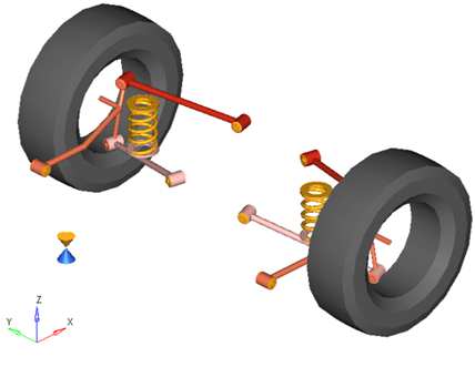
Figure 1. Rear Trailing Arm Suspension
Model Use
- The wheel body represents the mass and inertia of the tire and the rim.
- The wheel hub body represents the mass and inertia of other rotating bodies such as a brake rotor, but not the half-shafts if the suspension is driven. The wheel hub and brake rotor have no associated graphics.
- The wheel and wheel hub parts use the Wheel CG location as the center of gravity.
- Each body’s Center of Gravity (CG) is estimated from the body’s geometry. The formulas are coded into the point panel and can be seen via the graphical user interface. If more accurate CG locations are available they should be used.
- A wide variety of combinations of suspensions and subsystems can be built using the
Assembly Wizard. You are encouraged to build systems and
understand the resulting model using the graphical user interface.
When building a new suspension model, build the model with all of the optional systems (stabilizer bar, etc) included in the model. Immediately turn off the systems using the Project Browser and run an analysis on the base suspension to ensure it solves properly. As data becomes available for the optional systems; activate those systems and populate them with data.
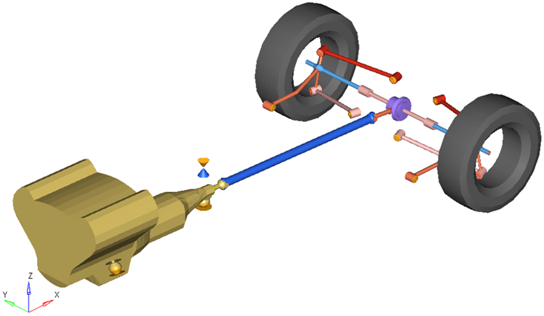
Figure 2. Rear-Half-Vehicle Model Employing a Trailing Arm Suspension
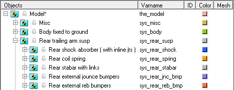
Figure 3. Browser View of a Rear-Half-Vehicle Model Systems and Subsystems Employing a Trailing Arm Suspension
Attachments
| Entity | Attaches To |
|---|---|
| Trailing Arm, Upper Link, Lower Links | Default: Sub-frame No subframe: Vehicle body No vehicle body: Ground |
Points
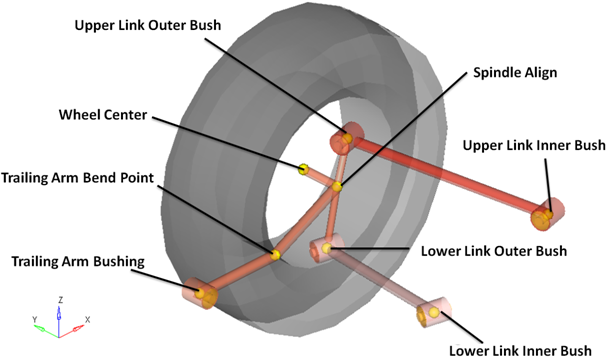
Figure 4. Right Side Principal Points – Rear Trailing Arm Suspension
Bodies
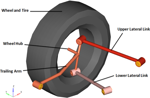
Figure 5. Right Side Bodies – Rear Trailing Arm Suspension
- The wheel hub body has no associated graphics and therefore is not visible in the image above.
- Only right side bodies are shown (as the left side bodies are symmetrical), and the coil spring has been omitted from the image above for clarity.
Bushings and Joints
| Label | Type | Body 1 | Body 2 | Point |
|---|---|---|---|---|
| Wheel Spindle Joint | Revolute | Wheel Hub | Trailing Arm | Wheel Center |
| Wheel Hub Fixed Joint | Fixed | Wheel | Wheel Hub | Wheel Center |
| Trailing Arm Bush | Ball | Trailing Arm | Vehicle Body | Trailing Arm Bush |
| Lower Link Outer Bush | Ball | Lower Lateral Link | Trailing Arm | Lower Link Outer Bush |
| Upper Link Outer Bush | Ball | Upper Lateral Link | Trailing Arm | Upper Link Outer Bush |
| Lower Link Inner Bush | Universal | Lower Lateral Link | Ground Body | Lower Link Inner Busy |
| Upper Link Inner Bush | Universal | Upper Lateral Link | Ground Body | Upper Link Inner Bush |
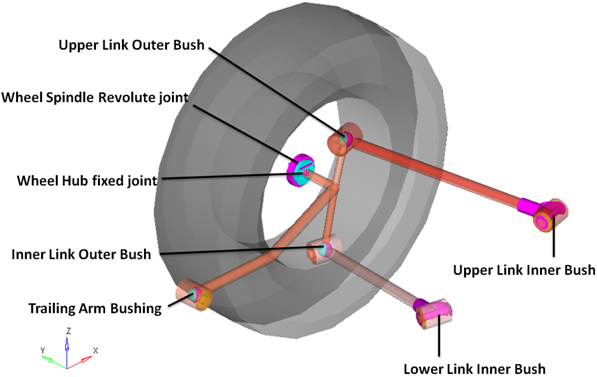
Figure 6. Right Side Joints and Bushings: Rear Trailing Arm Suspension