Rear MacPherson Strut
In a rear MacPherson struct suspension, the knuckle and wheel are located by a control arm, strut, and toe link. The coil spring is part of the strut and acts between the strut tube and the vehicle body. The spring’s axis typically is not parallel to the strut, but is offset to minimize the bending moment in the strut.
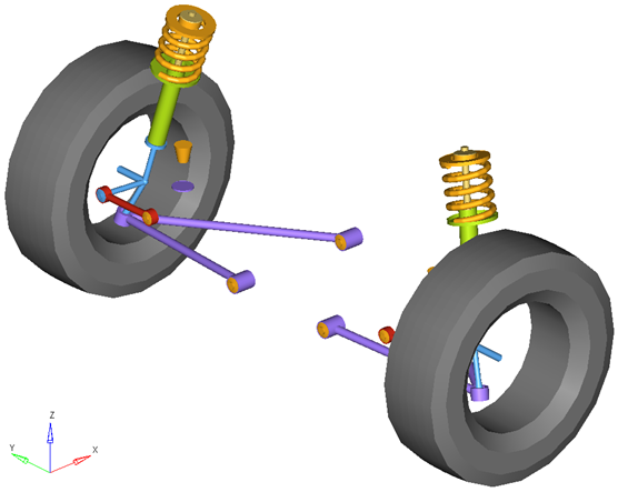
Figure 1. Rear MacPherson Strut Suspension
Model Use
- The wheel body represents the mass and inertia of the tire and the rim.
- The wheel hub body represents the mass and inertia of other rotating bodies such as a brake rotor, but not the half-shafts if the suspension is driven. The wheel hub and brake rotor have no associated graphics.
- The wheel and wheel hub parts use the Wheel Center location as the center of gravity.
- The lower control arm bushings are defined so their axes point at each other act like hinges on a door. If the front bushing is moved, both the front and rear bushing realign so they have the same axis of rotation.
- When the Compliant option is set to No (via the Option menu on the System/Assembly panel in MotionView) the lower control arm bushings are replaced with a single revolute joint located at the front bushing, with its rotational axis directed along the line from the front bushing to the rear bushing.
- A wide variety of combinations of suspensions and subsystems can be built using the
Assembly Wizard. You are encouraged to build systems and
understand the resulting model using the graphical user interface.
When building a new suspension model, build the model with all of the optional systems (stabilizer bar, etc) included in the model. Immediately turn off the systems using the Project Browser and run an analysis on the base suspension to ensure it solves properly. As data becomes available for the optional systems; activate those systems and populate them with data.
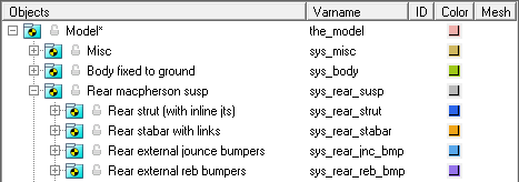
Figure 2. Browser View of a Rear-Half-Vehicle Model Systems and Subsystems Employing a Rear MacPherson Strut Suspension
Attachments
| Entity | Attaches To |
|---|---|
| Lower Arm | Default: Sub-frame No subframe: Vehicle body No vehicle body: Ground |
| Toe Link | Default: Rear sub-frame No rear subframe: Vehicle body No vehicle body: Ground |
| Strut-rod | Default: Vehicle body No vehicle body: Ground |
Points
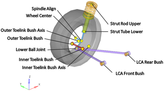
Figure 3. Right Side Principal Points – Rear MacPherson Strut Suspension
Bodies
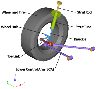
Figure 4. Right Side Bodies – Rear MacPherson Strut Suspension
Bushings and Joints
| Label | Type | Body 1 | Body 2 | Point | Notes |
|---|---|---|---|---|---|
| Lower Ball Joint | Spherical | Knuckle | Lower Control Arm | Lower Ball Joint | |
| Wheel Spindle | Revolute | Wheel Hub | Knuckle | Wheel Center | |
| Wheel Hub Fix Jt |
Fixed Joint | Wheel | Wheel Hub | Wheel Center | |
| LCA Front Bush | Bushing | Lower Control Arm | Subframe, Vehicle Body or Ground | LCA Front Bush | When the Compliant option is set to No, this bushing becomes a revolute joint. |
| LCA Rear Bush | Bushing | Lower Control Arm | Subframe, Vehicle Body or Ground | LCA Rear Bush | When the Compliant option is set to No, this bushing is deactivated. |
| Inner Toe Link Bush | Universal Joint | Toe Link | Subframe, Vehicle Body or Ground | Inner Toe Link Bush | |
| Outer Toe Link Bush | Spherical Joint | Toe Link | Knuckle | Outer Toe Link Bush | |
| Strut Tube Bottom Fixed Joint | Fixed Joint | Strut Tube | Knuckle | Strut Tube Lower | |
| Strut Upper Bush | Universal Joint | Strut Tube | Vehicle Body | Strut Upper |
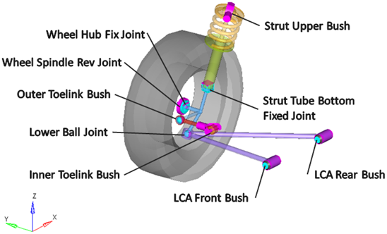
Figure 5. Right Side Joints and Bushings - Rear MacPherson Strut Suspension
External Files
The jounce bumper curve data and the rebound bumper curve data files are stored in the vehicle library and are referred to by this model. A new file should be created and substituted for these files when actual data is available.
Similar Suspensions
Rear Twist Beam
Rear Solid Axle w/Leafspring